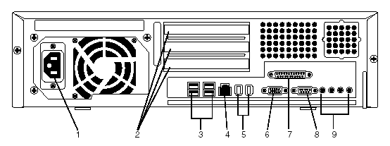

Make sure that the cables that connect your IR system to other devices and systems are firmly in place and functioning properly. The diagram below shows where cables connect to the back of the back of the Sun Blade 150 platform.

Port |
Function and Troubleshooting Considerations |
1 |
Power connector - Cable here provides power to the IR system. Disconnection from the plug results in loss of power and function. |
2 |
PCI card slots - Cables here connect NMS cards to the MultiVantage (DEFINITY) system or to digital telephony lines. Problems here may interfere with receiving and handling calls. |
3 |
USB connectors (four) - Two of these connectors are reserved for the keyboard and mouse that are part of the country kit. If a keyboard is not connected, and the IR system is rebooted, you may not be able to log into the IR system. Your organization may use the remaining USB connectors for other purposes. |
4 |
Twisted-pair Ethernet connector - Cable here connects the IR system to the LAN. Problems here may interfere with access to voice response applications, databases, proxy speech servers, and other IR system components that reside on servers on the LAN. If VoIP is in use, a loose connection here may cause problems with call processing. |
5 |
IEEE 1394 (Fireware) connectors (two). |
6 |
VGA video connector - The cable connects the video monitor to the IR system. Problems here may cause the video monitor to appear blank, even though the IRsystem is still processing calls. |
7 |
Parallel connector |
8 |
Serial connector (RS-232) - Cables here connect the IR system to the external modem, which controls dial up access to the system for Avaya support technicians. Problems here may mean that Avaya support technicians are unable to acccess the IR system for troubleshooting purposes. |
9 |
Audio module connectors |
You can also test port function. The Sun OpenBoot Diagnostics system performs root cause failure analysis on the ports. The Sun Blade 150 Service Manual explains how to run OpenBoot Diagnostic tests.