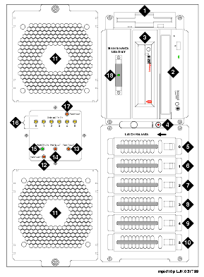
| Component |
Description |
Component |
Description |
| 1. |
Diskette drive |
3.5-inch, 1.44-MB high density; system configuration; diagnostic testing |
10. |
Empty hard disk drive carriage |
– |
| 2. |
CD-ROM drive |
Random access to the operating system, application software, and speech data |
11. |
Circuit card cage fan |
Cooling system |
| 3. |
Disk cartridge drive |
SCSI 2.0-GB; backup and restore; loading the system |
12. |
Fan fault LED |
LED; lights red for lower card cage fan failure |
| 4. |
Reset switch |
Push button; resets the MAP/100P CPU |
13. |
Card cage fan fault LED |
LED; lights red for a fan failure |
| 5. |
Hard disk drive 0 |
4.5-GB SCSI |
14. |
Power supply fault LED |
LED; lights red when power supply fan fails or power supply is removed |
| 6. |
Hard disk drive 1 |
4.5-GB SCSI |
15. |
Power-on LED |
LED; lights green when power is on |
| 7. |
Hard disk drive 2 |
4.5-GB SCSI |
16. |
Disk activity indicator
(per SCSI ID) |
LED; intermittently lights amber when associated disk is accessed and active |
| 8. |
Hard disk drive 3 |
4.5-GB SCSI |
17. |
Fan fault LED |
LED; lights red for upper card cage fan failure |
| 9. |
Hard disk drive 4 |
4.5-GB SCSI |
18. |
SCSI external active terminator |
External active terminator connected on the end of the CPU SCSI bus cable with LED indicator for power available |

