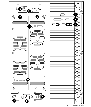
| Component |
Description |
| 1 |
Video circuit card
(PCI slot 1) |
Connector on the circuit card provides the interface between a monitor and the MAP/100P through a cable |
| 2 |
CPU
(slot 17) |
P5 200 MHz CPU with COM1 and parallel port connectors |
| 3 |
Remote maintenance circuit card (ISA slot 16) |
Provides access for remote maintenance |
| 4 |
ON/OFF power switch |
Rocker switch; turns power on or off to the MAP/100P |
| 5 |
AC power inlet receptacle |
3prong, 110V or 220V; connects the MAP/100P to the power source through a power cord |
| 6 |
Fuse, line |
AC line; 250V, 12 amp for US; 250V, 6.3 amp for international |
| 7 |
Power supply 1 |
110/220V autosensing, always required; provides +5, -5, +12, and -12 volts requirements |
| 8 |
Power supply 2 |
110/220V autosensing, always required; provides +5, -5, +12, and -12 volts requirements |
| 9 |
COM2
asynchronous port |
9pin male D subminiature; communicates with external devices |
| 10 |
Keyboard connector |
5pin female circular DIN to the MAP/100P |
| 11 |
Power supply status LED |
LED, power supply status; lights green when OK, lights red when faulty |

