![]()
|
|
|
|
|
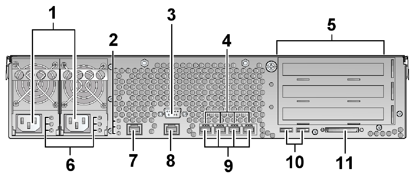
The back panel of the Sun Fire V240 is shown in the following figure. For more information about any of these connection types or indicators, see Sun Fire V210 and V240 Servers Administration Guide.
Item |
Connection type / Indicator |
Avaya IR system use |
1 |
Power inlets |
Dual redundant power supply inlets |
2 |
System LEDs |
The top LED is the System Activity LED. The middle LED is the Service LED. The bottom LED is the Locator LED. |
3 |
Serial port |
General purpose, asynchronous Labeled "10101" |
4 |
Ethernet activity LEDs |
For each Ethernet port:
|
5 |
PCI card slots |
For use of these PCI slots, see the Sun Fire V240 PCI slotting rules. |
6 |
Power Supply Unit (PSU) LEDs |
Each PSU has three status associated LEDs:
|
7 |
Network management port |
10Base-T Ethernet management domain interface |
8 |
Serial management port |
Used for serial management only – For general serial port usage, use the serial port labeled "10101" |
9 |
Ethernet ports |
All four are 10/100/1000Base-T |
10 |
USB ports |
USB1.1 compliant
|
11 |
External SCSI port |
Multimode Ultra 160SCSI interface |