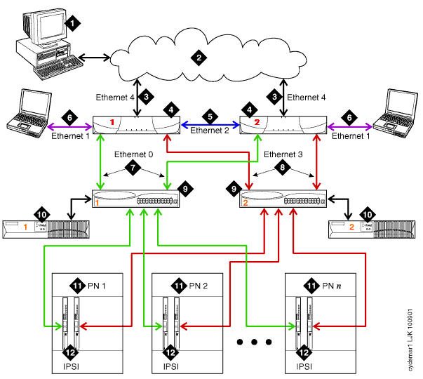
The Ethernet connections for a high- or critical-reliability setup of an Avaya S8700 Media Server for Multi-Connect Configuration are described below. This setup builds on the duplex configuration.

The critical-reliability aspect of this configuration (the duplication of the bearer channels among the port networks) is not shown because it works independently of the media server, and therefore is not administered through the web administration media server interface.
 Items 1 through 7 are identical for duplex and high- or
critical-reliability configurations.
Administration PC. The administrator typically accesses the S8700 servers over the corporate LAN.
Corporate LAN. The topology for the local area network varies significantly.
Corporate LAN interface: default Ethernet 4. The server's Ethernet link to the local area network, used for administration and (optionally) SNMP alarm notification.
Avaya S8700 Media Server. Two are always present, one in active mode and the other on standby.
Duplication interface: default Ethernet 2. The dedicated, direct Ethernet connection between the two required Avaya media servers.
Services interface: default Ethernet 1. The server's dedicated Ethernet connection to a laptop.
Network control A interface: default Ethernet 0. The server's Ethernet connection to 1 or 2 Ethernet switches. This private LAN carries the control signals for the S8700 port networks when possible. Control network A is considered the primary control network because it connects to the primary IPSI board in a port network.
Network control B interface: default Ethernet 3. The server's Ethernet connection to a duplicated set of 1 or 2 Ethernet switches.
This private LAN carries the control signals for the port networks when the primary control network is not available (for example, due to a hardware failure).
Control network B connects to the secondary IPSI board in a port network.
Ethernet switch. At least one is required to support each control network.
UPS. An uninterruptible power supply keeps each S8700 server and its set of Ethernet switches functional through brief power outages. Typically UPS 1 powers server 1 and its Ethernet switches, and UPS 2 powers server 2 and its Ethernet switches.
Port network (PN). Provides the telecommunications functions of the S8700 media server configuration. The port network configuration is identical to the duplex configuration, except that:
Each IPSI-connected port network contains a pair of IPSI boards, one primary board and a duplicate secondary board as a backup.
For a critical-reliability configuration, the bearer network among the port networks is also duplicated. This means that two EI boards or two ATM boards are present in each port network instead of just one.
IPSI. The Internet Protocol Server Interface (IPSI) circuit pack is duplicated in every IPSI-connected port network in a high- or critical-reliability configuration.
The primary IPSI is connected to control network A. It is the preferred IPSI because it has better control over activating the clock than the secondary IPSI.
The secondary IPSI is connected to control network B. This IPSI takes over in case of problems with the primary control network. The server regularly tests the duplicated IPSI to make sure it is ready for service, before returning control to the primary IPSI.
S8700 Multi-Connect duplex configuration
S8700 Multi-Connect preinstallation worksheet