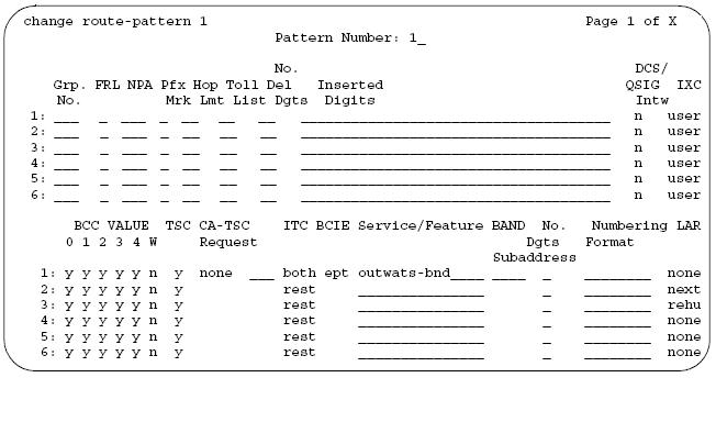
Preferences: Preference 1-6 on the top half of the Route Pattern are directly related to Preference 1-6 on the bottom half of the Route Pattern. Once the right to use ISDN feature has been turned on under Customer Options the bottom half of the route pattern will appear. This is referred to as a Split Route Pattern, and only calls routing over an ISDN trunk will get additional information from the bottom half of the route pattern. This is a way of inserting information in the outgoing set-up message of an ISDN call.
Grp No.: Values are 1-99 - Trunk Group number associated with this row.
FRL: Facility Restriction Level - Values are 0-7 - Enter the Facility Restriction Level (FRL) associated with the entries on this row (preference). 0 is the least restrictive and 7 is the most restrictive. The calling party's FRL must be greater than or equal to this FRL to access the associated trunk-group. The calling party's FRL is assigned on their Class of Restriction (COR).
NPA: Not required for AAR calls. 3-digit number. Enter the 3-digit Numbering Plan Area (NPA) (or area code) for the terminating endpoint of the trunk group. For WATS trunks, the terminating NPA is the same as the home NPA unless the Local Exchange Carrier requires 10 digits for local NPA calls.
Pfx Mrk: Not required for AAR. For ARS, enter a number from 0 to 4 or blank. Prefix Marks set the requirements for sending a prefix digit 1, indicating a long distance call. Prefix Marks apply to 7 or 10 digit Direct Distance Dialing (DDD) public network calls. A prefix digit 1 is sent only when call type (on ARS Analysis form) is foreign number plan area (FNPA) or home numbering plan area (HNPA). See Attachment for the Prefix mark chart and how numbers will be out pulsed.
- Prefix Mark 2 & 3 refer to the Toll List on route pattern. This was used primarily on older version of switches, like G1's and S75's. In newer software releases the ARS Analysis table allows you to be specific right down to the last digit on the dial string. If you see Toll list still being used it is usually because a customer has upgraded from a G1/S75 somewhere along the way. It is recommended that the translations be cleaned up.
Hop Lmt: Usually used for private networking. A hop is when a call tandems through a switch to another destination. Limiting the number of hops prevents circular hunting, which ties up trunk facilities without ever completing the call. DEFINITY ECS blocks a hop equal to or greater than the number you enter. If left blank there is no limit to the amount of times a call can tandem through a switch.
Toll List: Not required for AAR. Values are 1 to 32. You must complete this field if Prefix Mark is 2 or3. Again, keep in mind that these type of translations originated in earlier software releases, you may want to recommend to the customer that the translations be cleaned up.
-
The syntax for looking up this form is "change ars toll (toll list#) then : then (area code dialed) for example, if toll list was 8 and area code was 970 the syntax would be "change ars toll 8:970", you would now be looking at the 900 table for all area codes in the 900 range. Look at 70, if there is Y then the 1 would be out pulsed, if there is a N then the 1 will NOT be out pulsed.
No. Del Digits: Value is 0-32. Enter the total number of digits you want the system to delete before it sends the number out on the trunk. Use for calls that route:
-
to or through a remote switch
-
over tie trunks to a private network switch
-
over Central Office (CO) trunks to the serving CO
-
International calls routing over an ISDN facility
Inserted Digits: Enter the digits you want inserted for routing. The switch can send up to 52 digits. This includes up to 36 digits you may enter here plus up to 18-digits originally dialed. Special symbols count as two digits each.
Special symbols:
* When * is in the route pattern and the outgoing trunk is signaling type “mf”, the MFC tone for the “end-of- digits” is sent out to the CO in place of the *.
# When # is in the route pattern and the outgoing trunk is signaling type “mf”, the MFC tone for the “end-of-digits” is sent out to the CO in place of the #.
‘,’ Use 2 places. Creates a 1.5 second pause between digits being sent. Do not use as the first character in the string unless absolutely necessary. Misuse can result in some calls, such as Abbreviated Dialing or Last Number Dialed, not completing.
+ Wait for dial tone up to the Off Premises Tone Detection Timer and then send digits or intercept tone based on Out Pulse Without Tone y/n on the Feature-Related System Parameters screen.
% Start End-to-End Signaling.
! Wait for dial tone without timeout and then send DTMF digits.
& Wait for ANI (used for Russian pulse trunks)
DCS/QSIG Intw: This field only appears if the Interworking with DCS field on the Customer Options screen is set to y. Enter Y to enable the feature.
IXC: Inter-Exchange Carrier (IXC) identifies the carrier, such as AT&T, used for calls that route via an IXC, and for Call Detail Recording (CDR). This field appears when the ISDN-PRI or ISDN-BRI Trunks field is y on the System-Parameters Customer-Options screen.
-
user For presubscribed carrier. Used when an IXC is not specified.
-
none This field must be none for non-ISDN trunk groups and for Bellcore NI-2 Operator Service Access. If you need to send an IXC code for a non-ISDN trunk group, enter the IXC code in the Inserted Digits field.
The bottom half of the route pattern only applies to calls that route over an ISDN facility!
BCC Value: Bearer Capability Class (BCC) identifies the type of call appropriate for this trunk group, such as voice calls and different types of data calls. This field appears when the ISDN-PRI or ISDN-BRI Trunks field is y on the System-Parameters Customer-Options screen.
-
Enter y in appropriate BCC column (0, 1, 2, 3, 4, or W) if the BCC is valid for the associated route pattern (meaning a call with the BCC value set to yes is allowed to route over this trunk preference. if set to know that BCC value will be directed to a different preference and if no preferences are available, the call will be denied.
-
A trunk group preference may have more than one BCC.
-
BCC Values are programmed into software and can not be changed.
The follow table explains where BCC values are assigned
BCC Value Description
TSC: Set TSC to y for feature transparency on DCS+ calls and to use QSIG Call Completion.
CA-TSC: Use CA-TSC on ISDN B-channel connections.
Valid entries Usage
ITC (Information Transfer Capability): Use Information Transfer Capability (ITC) to identify the type of data transmission or traffic that this routing preference can carry. The ITC applies only to data calls (BCC 1 through 4).
BCIE (Bearer Capability Information Element): Use BCIE to determine how to create the ITC codepoint in the setup message. This field applies to ISDN trunks and appears if ITC isboth.
- ept (endpoint)
-
unr (unrestricted)
SERVICE/FEATURE: Enter up to 15 characters to identify the Service/Feature carried by the information element (IE) in a call in this route pattern. This field is required by Call-by-Call(CBC) Service Selection, and Network Call Redirection and Transfer. The Trunk Group must be set to CBC in order for a value to be assigned.
Valid entries__
-
accunet multiquest sdn (Enter to allow Network Call Redirection/Transfer)
-
i800 operator sub-operator
-
inwats oper-lds(operator and lds) sub-op-lds (sub-operator and lds)
-
lds oper-meg(operator and megacon) sub-op-meg(sub-operator and megacom)
-
mega800 oper-sdn(operator and sdn) sub-op-sdn(sub-operator and sdn)
-
megacom outwats-bnd wats-max-bnd
Band: Enter a number that represents the OUTWATS band number (US only). WATS is a voice-grade service that provides both voice and low-speed data transmission calls to defined areas (bands) for a flat rate charge 0.
No. Dgts Subaddress: Allows a caller to reach a number where switch digit processing deletes the dialed number and inserts the listed directory number (LDN). The LDN then is sent to the destination address and the dialed extension is sent in the calling party subaddress information element (IE). At the receiving end, the call terminates to the user indicated by the subaddress number instead of the attendant.
Valid entries__
Numbering Format: This field applies only to ISDN trunk groups. Enter a value from table below. This field specifies the format of the routing number used for the trunk group for this preference.
LAR: Enter the routing-preference for Look Ahead Routing.
Valid entries__
-
next Go to the next routing preference and attempt the call again.
-
rehu Rehunt within the current routing-preference for another trunk to attempt the call again.
-
none Look Ahead Routing is not enabled for the preference.