

|
|
|
The CNA system needs three separate channels of communication through your network, one for each of the following purposes:
See Figure 1.
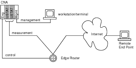
The management connectivity layer needs only as much access to your network as you want to give it, based on an assessment of who you want to be able to use the CNA web and command line interfaces. Management access to the device is through the management ethernet port.
The measurement layer must be able to communicate through your edge routers with traffic endpoints, either surfers on the other side of the Internet cloud or your remote VPN sites. USTAT modules and the EFC module must be connected to interfaces on the edge routers. These connections require some form of policy-based routing (PBR). Traffic can be channeled through a GRE tunnel, a VLAN, or a dedicated physical interface, for example. If you use a dedicated physical interface, there can be no routed hops between the CNA port and the edge router. The addresses configured on the CNA system for this purpose (called VIPs, or virtual IP addresses) must not be subject to Network Address Translation (NAT).
The control layer must be able to establish an iBGP peering relationship with your edge routers. TCP connections will be opened between the CNA system to the edge routers. Basic IP is sufficient for this layer. You may also elect to configure active probes using ICMP responses. BGP peering occurs on the engine module.
As long as these conditions are met, it doesn’t matter how you physically connect the CNA system into your network.
There are three basic configurations possible, each with its own trade-offs to be considered.
|
|
|