|
The back view of the S3400-H server varies, depending on the type
of motherboard and redundant power supply that is installed. Note
the configuration that your server uses:
Note: An S3400-H with an integrated video and LAN always uses side-by-side
redundant power supplies. An S3400-H with a nonintegrated video and
LAN usually uses vertically stacked redundant power supplies, although
it might use the side-by-side model.
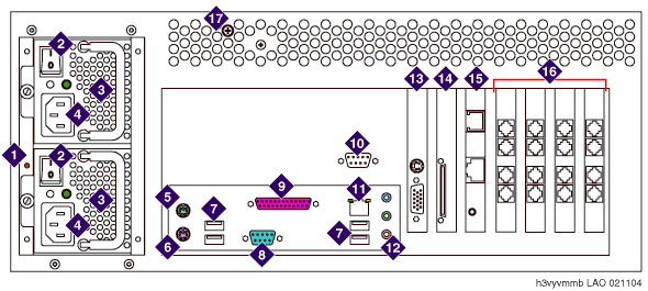
S3400-H with vertically stacked power supplies
and a nonintegrated video and LAN

| 1 |
Reset
switch for faulty power supply alarm |
| 2 |
Power
supply on/off switch |
| 3 |
Redundant
power supply |
| 4 |
AC
power receptacle |
| 5 |
Mouse
connector |
| 6 |
Keyboard
connector |
| 7 |
USB
ports |
| 8 |
Serial
port (COM1) |
| 9 |
Parallel
port (not used) |
| 10 |
Serial
port (COM2), connects to RMB |
| 11 |
Corporate
LAN interface |
| 12 |
Audio
connectors (not used) |
| 13 |
Video
card (contains monitor connector) |
| 14 |
SCSI
RAID controller card |
| 15 |
Remote
Maintenance Board (connects to analog line for alarm reporting
and servicing; international versions require an external modem) |
| 16 |
Analog
voice cards |
| 17 |
Latch
for top cover |
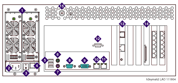
S3400-H with side-by-side power supplies and
an integrated video and LAN

| 1 |
Redundant power supply |
| 2 |
AC power receptacle |
| 3 |
Power supply on/off switch |
| 4 |
Reset switch for faulty power supply alarm |
| 5 |
USB ports |
| 6 |
Mouse connector |
| 7 |
Keyboard connector |
| 8 |
Serial port (COM1) |
| 9 |
Video connector |
| 10 |
Corporate LAN interface |
| 11 |
LAN interface (not used) |
| 12 |
Serial port (COM2), used for Remote Maintenance Board (RMB) |
| 13 |
Remote
Maintenance Board |
| 14 |
SCSI
RAID controller card |
| 15 |
Latch for top cover |
Top of page
|

