|
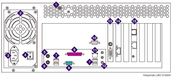
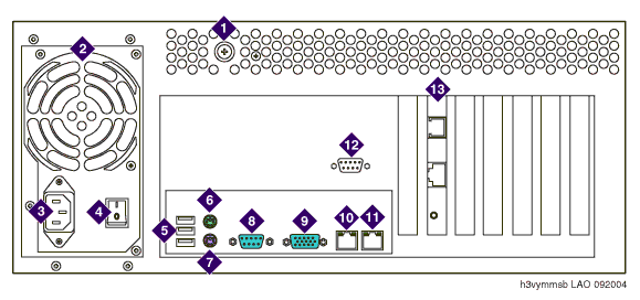
The back view of the MSS-S varies, depending on the type of motherboard
that is installed. The type of motherboard affects where cables
are connected.
Note the configuration that your model of MSS-S uses:
MSS-S with nonintegrated video and LAN

|
1
|
Latch for top cover |
|
2
|
Power supply |
|
3
|
AC power receptacle |
|
4
|
Power supply on/off switch |
|
5
|
Mouse connector |
|
6
|
Keyboard connector |
|
7
|
USB ports |
|
8
|
Serial port (COM1) |
|
9
|
Parallel port (not used) |
|
10
|
Serial port (COM2), used for the Remote Maintenance
Board (RMB) |
|
11
|
Corporate LAN interface |
|
12
|
Audio connectors (not used) |
|
13
|
Video card (contains monitor connector) |
|
14
|
Network interface card (used for the private LAN
to the Avaya MASs) |
|
15
|
Remote Maintenance Board (Connects to analog line
for alarm reporting and servicing. International versions require
an external modem.) |
MSS-S with integrated video and LAN

|
1
|
Latch for top cover |
|
2
|
Power supply |
|
3
|
AC power receptacle |
|
4
|
Power supply on/off switch |
|
5
|
USB ports |
|
6
|
Mouse connector |
|
7
|
Keyboard connector |
|
8
|
Serial port (COM1) |
|
9
|
Video connector |
|
10
|
Corporate LAN interface |
|
11
|
Private LAN interface |
|
12
|
Serial port (COM2), used for the Remote Maintenance
Board (RMB) |
|
13
|
Remote Maintenance Board (Connects to analog line
for alarm reporting and servicing. International versions require
an external modem.) |
Top of page
|

