|
The internal view of the MSS-S varies, depending on the type of
motherboard that is installed. The type of motherboard affects where
the cables and circuit boards are connected.
Note the configuration that your model of MSS-S uses:
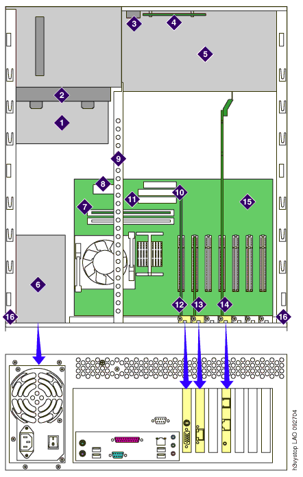
MSS-S with nonintegrated video and LAN
|
1 DVD-RAM drive
2 Drive cage
3 Power switch
4 LED panel (contains reset switch)
5 Chassis fan housing
6 Power supply
7 Memory module (DIMM card)
8 Main power connector
9 Inside rail (used for pushbutton-type circuit
card hold-down bracket)
10 Primary IDE connector
11 Secondary IDE connector
12 Video card
13 Network Interface Card (NIC)
14 Remote Maintenance Board (RMB)
15 Motherboard
16 Top cover guide rail
|
 |
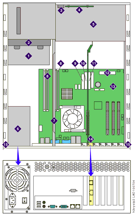
MSS-S with integrated video and LAN
|
1 DVD-RAM drive
2 Drive cage
3 Power switch
4 LED panel (contains reset switch)
5 Chassis fan housing
6 Power supply
7 Inside rail (used for lever-type circuit card
hold-down bracket)
8 Memory module (DIMM cards)
9 Main power connector
10 Secondary IDE connector
11 Primary IDE connector
12 Front panel connector
13 Motherboard
14 Remote Maintenance Board (RMB)
15 Top cover guide rail
|
 |
Top of page
|

