|
The internal view of the MAS varies, depending on the type of
motherboard that is installed. The type of motherboard affects where
port boards and cables are connected.
Note the configuration that your model of MAS uses:
|
Note: Any type of supported port boards (or no port
boards) might be installed in any MAS unit. All new MASs support
up to four (4) port boards. Only systems with a nonintegrated
video and LAN that were upgraded from Release 1 support five
(5) port boards, if five boards were installed before the
Release 2 upgrade.
|
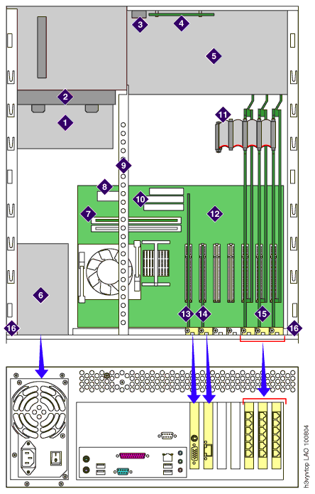
MAS with nonintegrated video and LAN
|
1 DVD player
2 Drive cage
3 Power switch
4 LED panel
5 Chassis fan housing
6 Power supply
7 Memory module (DIMM card)
8 Main power connector
9 Inside rail (used for pushbutton-type circuit
card hold-down bracket)
10 Primary IDE connector
11 CT bus cable
12 Motherboard
13 Video card
14 Network Interface Card (NIC)
15 Port boards (up to 5, depending on type)
16 Top cover guide rail
|
 |
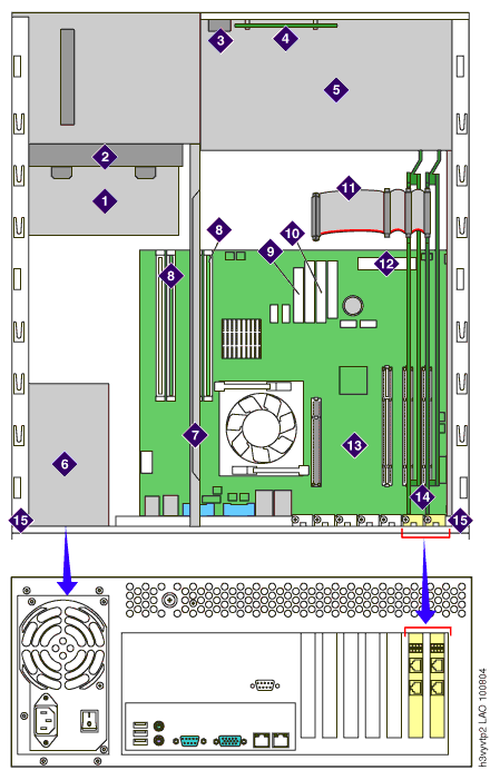
MAS with integrated video and LAN
|
1 DVD player
2 Drive cage
3 Power switch
4 LED panel
5 Chassis fan housing
6 Power supply
7 Inside rail (used for lever-type circuit card
hold-down bracket)
8 Memory module (DIMM cards)
9 Main power connector
10 Primary IDE connector
11 CT bus cable
12 Front panel connector
13 Motherboard
14 Port boards (up to 4, depending on type)
15 Top cover guide rail
|
 |
Top of page
|

