|
|
|
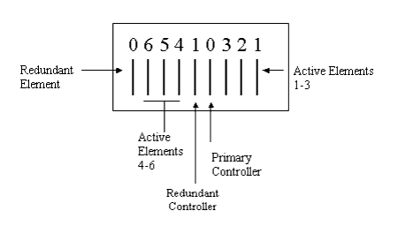
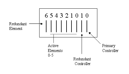
Controllers and Elements are located at the rear of the switches. When the redundant controller and element are installed, the backplane consists of the following parts (Figure�84 or Figure�85):
Figure�84:�Layout of the Redundant Backplane for P580 Chassis

Figure�85:�Layout of the Redundant Backplane for P882 Chassis

The Avaya Multiservice switches are equipped with diagnostics to:
If the Active supervisor fails, the Standby supervisor assumes supervisor operation. Information about a failed Supervisor (CPU) displays in the CPU Redundancy Status Web page.
If the Primary controller fails, the redundant controller takes over switch controller operation. When an element fails, diagnostics run automatically to test the hardware. Information about a failed controller or element displays in the Switch Fabric Status Web page. The redundant element takes over the function of the failed element until it is replaced.
Note: In the event that the Primary switch controller fails, the switch will reset and record an entry of the event in the shutdown log.
If the Active element fails, the Active and Standby Supervisor modules can no longer communicate, or be synchronized. No health messages will be passed. However, the Standby Supervisor module will become Active if the current Active Supervisor module fails.
|
|
|