Replacing the S8300 Media Server
The S8300 Media Server contains a Lithium/Manganese Dioxide battery.
CAUTION: Risk of explosion if battery is replaced by an incorrect type. Dispose of used batteries according to the instructions.
Note: The S8300 Media Server is inserted into the G700 Slot V1 whether it is the primary server or a local survivable backup. The S8300 Media Server can only be inserted in Slot V1 on the left side of the G700. The LED module must be pulled from its housing to provide clearance for the S8300 Media Server.
Replacing the S8300 Media Server in Slot V1 of the G700
Begin _____________________
- When removing the S8300, initiate a shutdown process by first depressing the button (for a few seconds) located next to the fourth GREEN "Ok-to-Remove" LED (specific to the S8300). This LED will first blink; then go steady. Once steady, this GREEN LED indicates that the disk drive has been parked properly and is ready to be removed.
- Undo the 2 captive screws.
- Disengage the LED module and remove it from the G700.
When you insert the S8300 Media Server into its slot on the left side of the G700, you must pull out the LED module to provide clearance for the S8300 Media Server.
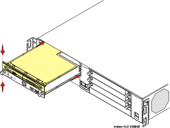
- Engage both sides of the S8300 Media Server module in the interior guides and guide the module halfway into the chassis.
Once the S8300 Media Server is engaged in the guides and inserted halfway into the chassis, the LED module should be engaged in its guides, and the two units should be pushed into place together.
- Align the LED module in its guides and gently push it into place, keeping the LED module safely within its guides and maintaining an even pressure to assure that the module does not become twisted or disengage from the guides.
Guide the longer, left side of the LED module into the chassis until the shorter, right edge of the module can engage in its guides. (Figure 1)
Figure 1. Align the LED module and the S8300 Media Server
- Push steadily and firmly until the faceplates of the S8300 Media Server and the LED module are even and then push the two units into the housing together.
- Apply firm pressure to engage the connectors.
The connector has different length pins. The long pins will engage first to provide grounding. Medium length and short pins will provide power and signal.
- Tighten the captive screws on the S8300 Media Server module.(Figure 2)
WARNING:
To prevent access to electrical hazards by unauthorized personnel and to ensure continued compliance to international radiated emissions requirements, all captive screws must be securely tightened such that they cannot be loosened without the use of a tool.
Figure 2. Tighten Screws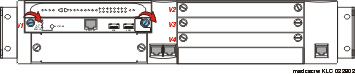
End _______________________