E1/T1 Media Module
The E1/T1 Media Module has a total of four LEDs. The E1/T1 Media Module has three LEDs on its faceplate, which are under software control. Table 107 shows their color and faceplate positions.
Table 107. Software-Controlled�E1/T1�LEDs �
| Color |
Location |
Description |
| RED |
Top |
Upon power-up, this LED is turned on. Upon passing diagnostics this LED is turned off. During normal circuit pack operation this LED is not turned on except for certain alarm states. |
| GREEN |
Middle |
During power-up self-testing and maintenance testing requested by the SPE, this LED is turned on. |
| YELLOW |
Bottom |
This LED indicates that the clock is synchronized with a source (usually the Central Office). The LED is blinking 2700 ms ON and 300 ms OFF. This is the most common condition.
The opposite blinking of the YELLOW LED is 300 ms ON and 2700 ms OFF. This is an error condition, and indicates that the MM710 E1/T1 Media Module is not synchronized with a clock.
An infrequent occurrence is a steady YELLOW LED. This indicates in-use activity, only when clock synchronization is set to local. |
The E1/T1 Media Module has a fourth GREEN SIG LED that indicates whether the link to the Central Office (CO) is up (equivalent to the TN464F circuit pack Status 3 GREEN LED). See Figure 18.
Note: Power-up and alarm states are the only conditions where hardware sets the state of the LEDs independent of ANGEL firmware control.
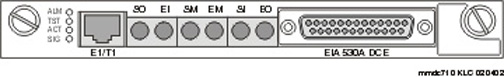
Figure 18. E1/T1 Media Module LEDs
The supported portion of the LED Control message allows software to change the status of the three standard LEDs on the E1/T1 Media Module faceplate. The exceptions to letting software turn off the LEDs are:
- The board is in reset (Red LED remains on)
- A call is up (Yellow LED remains on while the E1 line is in-frame and at least one voice/data call is up)
- During board reset initialization testing (Green LED remains on until initialization testing is complete).
Note: For ISDN operation, the Yellow LED will be turned on if ANY port has an active TDM connection (including the D-channel).
Synchronization
Clock synchronization is set via the Media Gateway Processor (MGP) command line interface (CLI). The command (in 'configure' mode) set sync interface {primary | secondary} {<mmID> | [<portID>]} defines a potential stratum clock source (E1/T1 Media Module, ISDN-BRI).,
where <mmID> is the Media Module ID of a MM stratum clock source of the form "vn", where "n is the MM slot number, and
For the MM720 BRI Media Module, <portID> is formed by combining the mmID of the MM to the 2-digit port number of the BRI port.
By setting the clock source to primary, normal failover will occur. Setting the source to secondary overrides normal failover, generates a trap, and asserts a fault. The identity of the current sync source in use is not stored in peristent storage. Persistent storage is used to preserve the parameters set by this command.
Control of which reference source is the "Active" source is accomplished by issuing the command set sync interface {primary | secondary}. If 'secondary' is chosen, then the secondary source becomes "Active", and the primary becomes "standby", and, in addition, fallback to the primary source will not occur if or when it becomes available.
If neither primary nor secondary sources are identified, then the local clock becomes "Active".
When a MM710 Media Module is driving a clock sync source line to the G700 main clock, the Yellow LED does not indicate port activity, but instead indicates that the MM710 is the sync source as follows:
- If the incoming signal is good, the YELLOW LED is driven on for three seconds and off for 200 milliseconds.
- If the incoming signal is lost and the sync line cannot be driven, the YELLOW LED is alternately off for three seconds and on for 200 milliseconds.
- If the YELLOW LED is on for 2.7 seconds and off for.3 seconds, the toneclock synchronizer is in "active" mode and an external synchronization source is being used as a synchronization reference.
- If the YELLOW LED is on 0.3 seconds and off 2.7 seconds, the toneclock synchronizer is in "active" mode and the internal (onboard) high accuracy clock is being used as a synchronization reference.
- If the UDS1 receives a downlink CCMS message to stop driving the clock sync lines, the YELLOW LED reverts back to indicating port activity.
Note: Unless otherwise indicated, the following commands issue from the G700 MGP CLI.
Table 108. mgp-001-1(configure)# show sync timing
| SOURCE |
MM |
STATUS |
FAILURE
|
| Primary |
|
Not Configured |
|
| Secondary |
|
Not Configured |
|
| Local |
v0 |
Active |
None |
| Comment: No failures, SIG GREEN on and ACT on when trunk is seized |
Table 109. mgp-001-1(configure)# set sync interface primary v4
mgp-001-1(configure)# show sync timing
| SOURCE |
MM |
STATUS |
FAILURE
|
| Primary |
V4 |
Locked OUt |
None |
| Secondary |
|
Not Configured |
|
| Local |
V0 |
Active |
None |
| Comment: No failures, Sig is green and ACT On 2.7s off 0.3s Note that the MM710 in slot 4 has been declared to be the primary sync source but it is not active until the next command is issued |
Table 110. mgp-001-1(configure)# set syn source primary
mgp-001-1(configure)# show sync timing
| SOURCE |
MM |
STATUS |
FAILURE
|
| Primary |
V4 |
Active |
None |
| Secondary |
|
Not Configured |
|
| Local |
V0 |
Standby |
None |
| Comment: The ACT LED does not change its behavior. |
To test for slippage, from the SAT issue the command:
test mo logical 4255 physical 1v4 test 144
The results from the above command are given in Table 111:
Table 111. TEST RESULTS
| Port |
Maintenance Name |
Alt. Name |
Test No. Result |
Error Code |
| 001V4 |
MG-DS1 |
144 |
PASS |
|
| Command successfully completed |
|
If a secondary is similarly provisioned:
Table 112. mgp-001-1(configure)# set syn int sec v3
mgp-001-1(configure)# sho syn tim
| SOURCE |
MM |
STATUS |
FAILURE |
| Primary |
V4 |
Active |
None |
| Secondary |
V3 |
Standby |
None |
| Local |
V0 |
Standby |
None |
To activate the secondary, the following is similarly done:
Table 113. mgp-001-1(configure)# set syn source sec
mgp-001-1(configure)# sho syn tim
| SOURCE |
MM |
STATUS |
FAILURE |
| Primary |
V4 |
Locked Out |
None |
| Secondary |
V3 |
Active |
None |
| Local |
V0 |
Standby |
None |
| Note: The system uses one clock at a time only: therefore only the secondary is active and the primary is locked out. |
To activate local the following is done:
Table 114. mgp-001-1(configure)# set syn sou local
mgp-001-1(configure)# sho syn tim
| SOURCE |
MM |
STATUS |
FAILURE |
| Primary |
V4 |
Locked Out |
None |
| Secondary |
V3 |
Locked Out |
None |
| Local |
V0 |
Active |
None |
To reactivate the primary, the following is done:
Table 115. mgp-001-1(configure)# set syn sou pri
mgp-001-1(configure)# sho syn tim
| SOURCE |
MM |
STATUS |
FAILURE |
| Primary |
V4 |
Active |
None |
| Secondary |
V3 |
Standby |
None |
| Local |
V0 |
Standby |
None |
| Note that secondary and local are standby because they are provisioned as fail overs. |
If the T1 physical connection were removed, then the secondary becomes active and the primary reports a failure.
Table 116. mgp-001-1(configure)# sho syn tim
| SOURCE |
MM |
STATUS |
FAILURE |
| Primary |
V4 |
Standby |
Out of Lock |
| Secondary |
V3 |
Active |
None |
| Local |
V0 |
Standby |
None |
| Note that secondary and local are standby because they are provisioned as fail overs. |
Initialization
The E1/T1 Media Module LEDs behave in the following manner during initialization:
- The Angel provides a visual indication of the board's status through the three board LEDs.
- During initialization the YELLOW LED is held off, while the RED and GREEN LEDs are on during the entire initialization sequence.
- Upon power up or reset, if only the RED LED comes on, the Angel processor is dead or the board is being held permanently in reset.
- Upon completion of the diagnostics and initialization, the GREEN LED turns off.
- If the initialization tests fail, the RED LED remains on.
- If the tests all pass, then all LEDs are extinguished until switch software starts using the board.
After a successful initialization sequence, the LEDs are controlled as follows:
- The Angel lights the YELLOW LED when there is at least one non-idle trunk. If switch software sent a message to drive the clock sync signals, the YELLOW LED indicates this instead of the port busy/idle status.
- The SPE may independently light and extinguish the three LEDs through downlink LED Control messages, subject to the constraint that it may not turn off a YELLOW LED turned on by the Angel as a result of port activity.
- If the NCE+ resets the board for any reason and does not release the board from reset, the RED LED lights and the YELLOW and GREEN LEDs are held off.