DEFINITY Made Easy Tools
Issue 3, December 2001
Install Telecommunications Cabling
Patch Cord/Jumper Installation and Administration
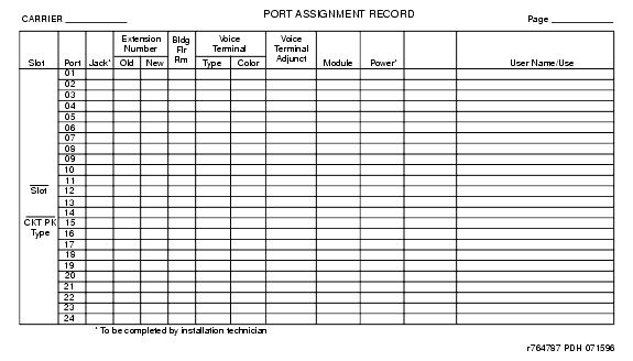
Before starting the patch cord installation, obtain a copy of the Port Assignment Record forms from the customer or marketing representative. See Port Assignment Record Form. These forms contain the port assignments and identify the extension numbers ( Terminal No.) of the telephones/voice terminals. Enter the jack assignments at the equipment room and indicate if adjunct power is required and where it is provided (MDF, site/satellite closet, or information outlet).
When satellite locations are provided, enter the satellite letter designation (A through F) and the jack appearance in the equipment room on the form. Also, enter the floor designation and/or building designation if appropriate. For 1-point administration, this entry is all that is required.
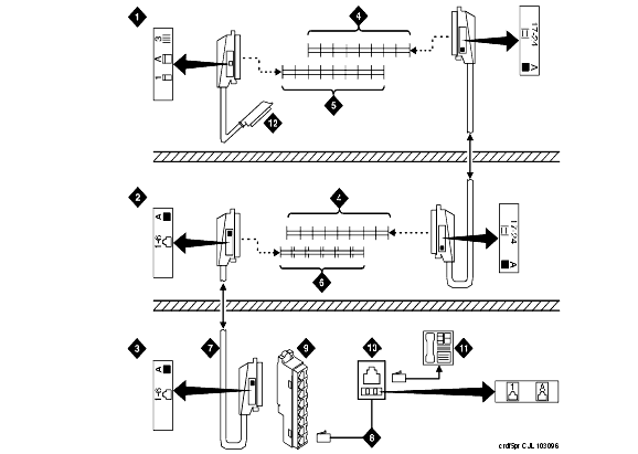
The white label identifying the terminal block row associated with circuits 17 to 24 connects to an identically labeled terminal block row at the satellite closet. See Example 3-Pair Labeling to Information Outlet. This is always the case for either 1-point or 2-point administration.
The satellite symbol must be installed at all connection points between the blue field and the information outlet. It must also be installed at the information outlet itself.
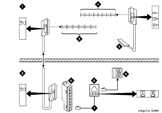
Example 4-Pair Labeling to Information Outlet shows an example labeling scheme for 4-pair circuits from the equipment room to the information outlets. The labeling scheme for 3-pair circuits from the MDF to a satellite location.
Port Assignment Record Form
Example 3-Pair Labeling to Information Outlet
Figure Notes:
- Equipment Room
- Satellite Location
- Work Location
- White Row on 110 Terminal Block
- Purple Row on 110 Terminal Block
- Blue Row on 110 Terminal Block
- Central Location for Terminals 1 through 6
- D-Inside Wire Cut Down to Connecting Block
- 258A Adapter
- Information Outlet
- Voice Terminal
- To Port Connector on Cabinet (Cabinet 1, Carrier A, Slot 03)
Example 4-Pair Labeling to Information Outlet
Figure Notes:
| Copyright� 2001 Avaya Inc. |
| Send comments to MadeEasy Development Team |
| Always check at the Made Easy Web site for the most current information. |


