DEFINITY Made Easy Tools
Issue 3, December 2001
Install and Wire Telephone Power Supply
Wire the 1146B Power Distribution Unit
Wire endpoints to the1146B while power from the 1145B is on. A red LED lights if its associated circuit is connected to shorted wiring or to a shorted terminal.
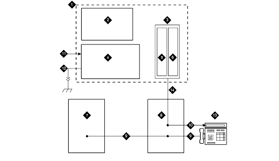
- Install cross-connect jumpers to wire from the unit (the label shows polarity) to Pins 7 and 8 of the appropriate information outlet. Route the wires through the clip provided on the unit. If a red LED is on, see Reset LEDs on Power Distribution Unit. See Typical Wiring to a Terminal.
- Mark lead destinations on the label next to each connector. Also mark the Unit Number and Connectivity information on the label.
Typical Wiring to a Terminal
Figure Notes:
- Power Supply Kit
- 2.5, 5.0, or 8.0 Amp Hour Battery
- 1146B Distribution Unit
- 1145B Power Supply
- Circuits 1-16
- Circuits 17-32
- Port Circuit
- Main Distribution Frame
- Modular Cord
- Pins 7 and 8 (Display Terminal Power)
- AC Input
- Installer-Provided Ground Wire
- ISDN/ Display System Protocol Terminal
- Circuits 1-32
| Copyright� 2001 Avaya Inc. |
| Send comments to MadeEasy Development Team |
| Always check at the Made Easy Web site for the most current information. |
