Digital Out-of-Building Voice Terminal Protection
Return to Task List
For information about specific protectors, see
Installing the ITW Linx Enhanced Protector
Installing the 4C3S-75 Enhanced Protector
Installing the Data Link Protector
Digital out-of-building voice terminals require protection at both building entrances. The 4C3S-75 Enhanced Protector and the ITW Linx Enhanced Protector can be used to protect digital voice terminals and digital line circuit packs. These units provide primary and sneak current protection. The 4C3S-75 is equipped with a heat coil for sneak current protection, and the ITW Linx is equipped with replaceable fuses for sneak current protection.
The 4C3S-75 may be used only with Vintage 14 or newer TN754 circuit packs or TN754B circuit packs. Digital Voice Circuit Protectors lists the approved protectors.
When possible, all new and reused wiring installations should use blocks that accept the standard 5-pin plug-in 4C3S-75 protector. However, there are reused wiring installations where this may not be cost effective. For these installations, the ITW Linx protector may be installed.
An example of this is where screw-type carbon block protectors -- or other non plug-compatible types -- are in place and it is too costly to re-terminate the outside plant cable on a 5-pin mounting block for only a few out-of-building terminals.
Installing the ITW Linx Enhanced Protector
The ITW Linx Enhanced Protector can be installed in series with existing primary protection. The ITW Linx Enhanced Protector mounts directly on connecting blocks and requires a separate ground bar.
Installing the 4C3S-75 Enhanced Protector
The 4C3S-75 protector cannot be installed in series with other types of primary protection. It must be installed as the only protection on the line entering the building. For the 4C3S-75 protector there are a variety of 25-, 50-, and 100-pair protector panels equipped with 110-type connecting blocks and/or RJ21X connectors.
Installing the Data Link Protector
Return to Task List
The maximum range for out-of-building digital voice terminals is 3400 feet when using 24 AWG (#5) (0.5 mm
2) wire and 2200 feet (670 m) when using 26 AWG (#4) (0.4 mm
2) wire. The range can be extended to 5000 feet (1524 m) using 24 AWG (#5) (0.5 mm
2) wire or 4000 feet (1220 m) using 26 AWG (#4) (0.4 mm
2) wire with the use of a data link protector. The protector is an isolating transformer used to remove phantom power on the system side and re-introduce it on the terminal side.
When a protector is used, the voice terminal must be locally powered by an external power supply or through the AC power cord provided with some of the 7400-type voice terminals. The protector is installed on the equipment side of the protection in both buildings.
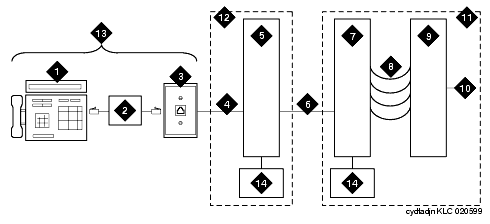
Refer to Example Adjunct Power Connections and Connections at Trunk/Auxiliary Field.
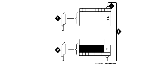
Refer to Example Adjunct Power Connections and Connections at Trunk/Auxiliary Field.
Example Adjunct Power Connections

Figure Notes:
-
Typical Display Telephone
-
Individual Power Supply (Such as 1151A1 or 1151A2)
- Information Outlet (Modular Jack)
- 4-Pair D-Inside Wire (DIW) Cable
- Satellite Site or Adapter Location
- 25-Pair D-Inside Wire (DIW) Cable
- Station Side of Main Distribution Frame (MDF)
- 100P6A Patch Cord or Jumpers
- System Side of Main Distribution Frame (MDF)
- 25-Pair Cable to System Cabinet (Analog Line Circuit Pack)
- Equipment Room
- Satellite Location
- Work Location
- Bulk Power Supply (Such as 1145B)
Connections at Trunk/Auxiliary Field

Figure Notes:
-
To Network Interface Facility
-
To Control Carrier Auxiliary Connector
-
One Pair of Wires
- Twenty-fifth Pair of RJ21X Network Interface Jack
Return to Task List

