DEFINITY Made Easy Tools
Issue 3, December 2001
Install and Wire Telephones
Connect a Typical Telephone
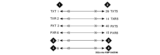
The 302C1 Attendant Console is used to describe a typical telephone connection. This information is typical of the 603E, 84xx (4-wire), and 94xx telephones.
The attendant console always requires auxiliary (adjunct) power (-48 VDC). Power is connected to the console through Pins 7 and 8 of the information outlet. Only three consoles can be powered by the system through the AUX connector. When possible, the primary console should be powered from the system so it has the same power failure backup as the system.
The maximum cabling distance for the console powered from the cabinet is 350 feet (100 meters).
The general steps to connect a telephone are:
- Choose a device to connect such as a 302C1 Attendant Console.
- Choose the port circuit pack and its carrier and slot number, such as cabinet 1, carrier C, slot 02.
- Choose a port circuit on the port circuit pack, such as Port 05.
- Install cross-connect jumpers to wire the terminal to the port circuit pack. See 302C1 to 4-wire DCP Wiring. This pinout is for the 4-wire Digital Line circuit pack.
