DEFINITY Made Easy Home Page Table of contents Previous page Next page Index Links Frequently asked questions
Go to Upgrades for si Go to Installation for MCC Go to Installation for SCC


Connecting Through a Channel Service Unit

Return to Task List

DS1 Converter Connections for T1 Service -- Part 2 shows a typical connection for a T1 line, and DS1 Converter Connections for 120-ohm E1 Service -- Part 2 shows a typical connection for an E1 line.
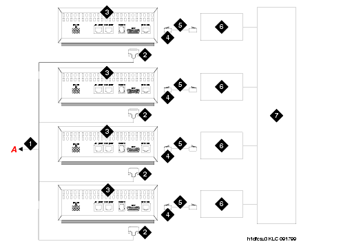
  1. Connect the H600-348 Quad Cable to the DTE jacks on each of the 4 CSUs.

  2. You may need an adapter cable to connect the H600-348 cable to the CSU (see Adapter Descriptions).

  3. Connect one end of the H600-383 cable to the network jack on the CSU and the other end to the smart jack.

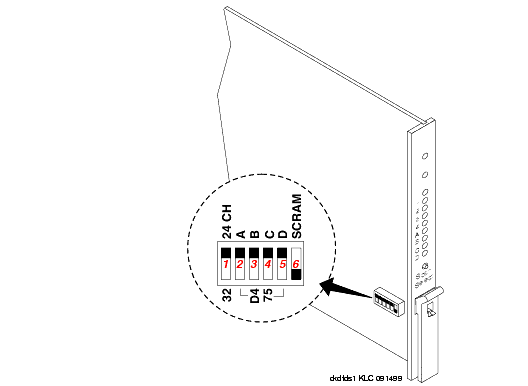
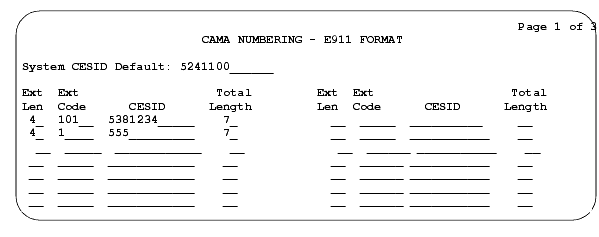
Connection to the remote-located system is the same as that shown in DS1 Converter Circuit Pack Switches and CAMA Numbering Format form.

Y Cable Lengths shows theY cable lengths.

The distinction between facility types is important when using TN1654 circuit packs. The facility used to carry control channel messages between the pair of DS1 converter circuit packs and all packet traffic is known as the primary facility. The facility used to backup and takeover for the primary facility in the event of primary facility failure is known as the secondary facility. The TN1654 allows either facility, A or B, to be a primary channel. The control channel is restricted to only the A or B facilities. This permits full 24-channel access (T1) or 31-channel access (E1) for facilities C and D to support user traffic.

DS1 Converter Connections for T1 Service -- Part 2

Figure Notes:
      1. H600-348 Quad Cable

      2. 15-Pin Male D Connectors (to DTE Jacks on CSU)

      3. Channel Service Unit (CSU)

      4. H600-383 Cable (RJ-48C to RJ-48C)

      5. Network Interface

      6. 700A Loopback Jack

      7. Cables

DS1 Converter Connections for 120-ohm E1 Service -- Part 2
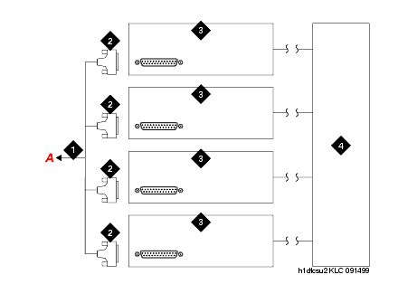
Figure Notes:
      1. H600-348 Quad Cable

      2. 15-pin male D connectors (to DTE jacks on customer-provided network-interface equipment)

      3. Customer-provided network-interface equipment

      4. Network interface

Adapter Descriptions
Type
Color
Description

Straight through

Black

Cable with a DB15 connector on one end and an RJ48 connector on the other

Rollover

Gray

Cable with a DB15 connector on one end and an RJ48 connector on the other

Null

Black

A DB15M to DB15F rollover/null adapter.

DS1 Converter Circuit Pack Switches

CAMA Numbering Format form

.

Y Cable Lengths
Length
Description

14 in. (35.6 cm)

TN1654 circuit pack to adjacent EI circuit pack or TN573B SNI circuit pack in same carrier

70 in. (178 cm)

TN1654 circuit pack to EI circuit pack or SNI circuit pack in another carrier

14 in. (35.6 cm)

TN1654 circuit pack to fiber optic transceiver (DC-powered cabinets only). This cable is for intercabinet cabling only.

Return to Task List


DEFINITY Made Easy Home Page Table of contents Previous page Next page Index Links Frequently asked questions
Go to Upgrades for si Go to Installation for MCC Go to Installation for SCC
Copyright 2001 Avaya Inc.
Send comments to MadeEasy Development Team


Always check at the Made Easy Web site for the most current information.