Install and Administer ISDN - BRI
Return to Task List
If adding the packet bus support and TN570s must be installed as part of that support, adding ISDN--BRI requires a service interruption. Notify the customer in advance as to when the addition will be carried out. See Add Packet Bus Support for R8si for further information.
This section provides information on
Task List: Installing ISDN - BRI
BRI Terminating Resistor Installation
Return to Task List
The resistors balance the cable plant between the receiver and the transmitter on the interface. When using the TN2198 ISDN-BRI 2-Wire U Interface circuit pack, an NT1 is required. A terminating resistor is always required near the terminal when the BRI S-type interface circuit pack (TN556 BRI 4-Wire S-NT Line circuit pack) is used (see
5ESS Switch Integrated Services Digital Network Customer Premises Planning Guide, 533-700-100).
The resistor is built into the NT1 and can be one of three values, depending on the configuration and the distance from the NT1 to the ISDN terminal. The resistor value is controlled from the NT1. A terminating resistor adapter may be needed near the terminal and can be placed in the satellite closet or work location.
See these BRI Terminating Resistor Topics:
Important Warning
Observe these precautions:
- Never install telephone wiring during a lightning storm.
- Never install telephone jacks in wet locations unless the jack is specifically designed for wet locations.
- Never touch uninsulated wires or terminals unless the telephone line has been disconnected at the network interface.
- Use caution when installing or modifying telephone lines.
Return to Task List
Terminating Resistor Adapter
8-Wide Terminating Resistor Adapter (440A4) shows an 8-pin 440A4 terminating resistor adapter. The adapter is three inches long with an 8-wide plug at one end, a short cord, and an 8-wide jack at the opposite end.
Closet-mounting the 110RA1-12 Terminating Resistor Block
The 110RA1-12 terminating resistor block is designed to mount in the telecommunications wire closet. It consists of twelve 2-pair circuits and provides the 100 Ohm termination used for ISDN-BRI circuits.
Terminating Resistor Block (110RA1-12) shows the wiring of the 110RA1-12. Three rows of 110D-4 connector blocks are mounted on a printed wire board along with circuit resistors and capacitors. The bottom row is designated as the input row and the top and middle rows are designated as the output rows. The circuit assembly is mounted on a standard 110A-100 pair mounting base. The 110RA1-12 is shipped with preprinted designation strips to simplify circuit identification and installation.
Typical Installation of Terminating Resistor Block Using Multi-point Connection shows the wiring connections for the 110RA1-12 terminal block. The TN556 BRI switch port is terminated to bottom row C.
For point-to-point wiring, the top row is connected to the blue station field. The pair connects from the 110RA1-12 to the standard 4-pair circuit. Pair 1 from the 110RA1-12 is connected to Pair 1 of the station field, and Pair 2 is connected to Pair 3 of the station field.
Two terminal basic multi-point applications are accommodated by connecting row B (output) to the second terminal common to the multi-point circuit.
Return to Task List
Installing Multi-point Adapters
Multi-point adapters are used to provide signal fanout of the T-interface. Fanout can be performed at the work station by the BR851-B Adapter (T-Adapter) or the Wiring Diagram of 367A Adapter. These adapters support more than one ISDN terminal per horizontal 4-pair D-inside wire (DIW). To support multiple horizontal runs, fanout must be performed in the satellite closet by a MDF with multiple common rows. The 110RA1-12 provides fanout for two horizontal runs and contains the 100 Ohm terminating resistor. This can be used for basic multi-point or point-to-point with terminating resistor in the closet. Other fanout blocks include the 110AB1-025M and the 110AB1-050M.
BR851-B Adapter (T-Adapter)
The BR851-B supports two terminals on one multi-point BRI at the work station. It is a T-shaped device used to fanout transmission and power. The BR851-B is an 8-pin device with a single plug and two jacks. See Wiring Diagram of BR851-B.
367A Adapter
The 367A is an 8-conductor adapter used at the work location to bridge 3 to 7 terminals. See Wiring Diagram of 367A Adapter.
Return to Task List
Basic Multi-point Installation Distances
Basic Multi-point with One Work Location provides cabling information for fan-out of ISDN-BRI multi-point installations. In Basic Multi-point with One Work Location, the terminating resistor is located in the satellite closet. All distances assume 24 AWG (#5) (0.5 mm
2) D-Inside Wire (DIW).
8-Wide Terminating Resistor Adapter (440A4)
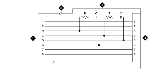
Figure Notes:
-
8-Wide Plug
-
Cord
-
Plastic Housing
-
8-Wide Jack
Terminating Resistor Block (110RA1-12)
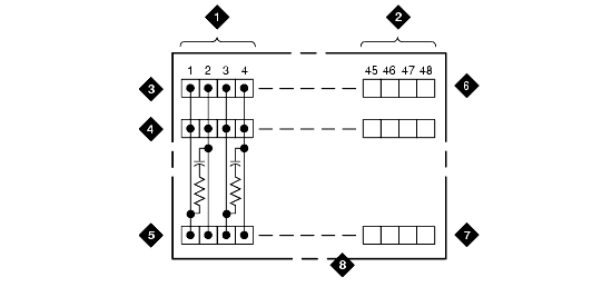
Figure Notes:
-
Circuit 1
-
Circuit 12
-
Output Row "A"
-
Output Row "B"
-
Input Row "C"
-
Only First Circuit Shown to All 12 Circuits (2APR) Per Block
-
110D-4 Connector Block
-
Printed Circuit Board Mounted on Standard 110A or 100APR Block
Typical Installation of Terminating Resistor Block Using Multi-point Connection

Figure Notes:
-
Part of Terminating Resistor Block
- White or Purple Field
-
Part of 4-Pair Blue Field
- From
ISDN T-interface Circuit (2-
Pair)
-
To ISDN S/T-interface Terminals
-
2-Pair Cross-Connect
-
Basic Multi-point Option
-
2-Pair Cross-Connect
-
4-Pair Horizontal Cables
-
Row "A"
-
Row "B"
-
Row "C"
Wiring Diagram of BR851-B
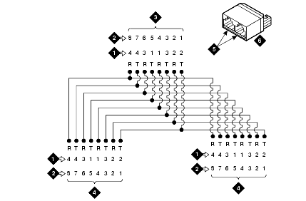
Figure Notes:
-
Wire Pairs
-
Pin Numbers
-
Modular Plug (Male)
-
Female
-
Two 8-pin Modular Jacks
-
T-Type Adapter
Wiring Diagram of 367A Adapter
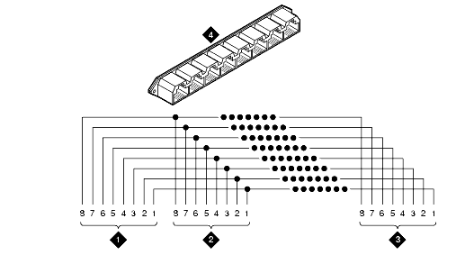
Figure Notes:
-
Jack 1
-
Jack 2
-
Jack 8
- 367A Adapter
Basic Multi-point with One Work Location
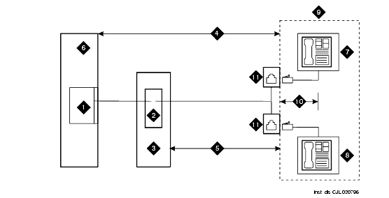
Figure Notes:
-
S-Interface Source (TN556)
-
Terminating Resistor
-
Satellite Closet
- Maximum Distance from S-Interface Source to Work Location (1600 Feet) (488 m)
- Maximum Distance From Terminating Resistor to Work Location (250 Feet) (76 m)
- System Cabinet
-
Terminating Endpoint 1
-
Terminating Endpoint 2
- Work Location
- Maximum Distance from Information Outlet to Terminating Endpoint (33 Feet) (10 m)
- Information Outlet


