DEFINITY Made Easy Tools
Issue 2, November 2000
Install and Connect Multi-Carrier Cabinets
Connect Power and Ground(s)
- Have a qualified electrician connect and route wires from the AC load center to the dedicated electrical outlet for the power distribution unit.
- Connect 1 end of a 6 AWG (#40) (16 mm 2) wire to the ground terminal block on the rear of the cabinet. See Power Distribution Unit (J58890CH).
- Route the CABINET GROUND wire to the AC load center single-point ground block and connect.
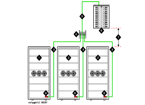
- Connect 1 end of a 6 AWG (#40) (16 mm 2) CABINET GROUND wire to the ground terminal block at the bottom rear of the EPN cabinet. See Typical Cabinet Grounding Wiring Diagram.
- Route the CABINET GROUND wire to the AC load center single-point ground and connect.
- Connect each remaining EPN cabinet to the AC load center single-point ground.
Power Distribution Unit (J58890CH)
Figure Notes:
- Connect small battery holdover cable (or temperature sensor cable from large battery cabinet) to J20
- Carrier Circuit Breakers
- Ground Terminal Block
- Connect -48 VDC Return - 1 AWG (50 mm 2) red cable here.
- Connect -48 VDC - 1 AWG (50 mm 2) black cable
- 1 AWG (50 mm 2) 50 ft (15.2 m) cable to large battery cabinet. For cables greater than 50 ft (15.2 m), contact your Lucent Technologies representative.
- Ground Terminal Block
- To AC load center or approved single-point ground block
Typical Cabinet Grounding Wiring Diagram
Figure Notes:
| Copyright� 2000 Avaya Inc |
| Send comments to MadeEasy Development Team |
| Always check at the Made Easy Web site for the most current information. |

