|
|
|
There are several reasons for replacing a Media Module:
The modules on the G700 are not inserted until the G700 registers with Avaya MultiVantage. Likewise, all Media Modules and associated Maintenance Objects are removed if the G700 link goes down.
The term 'board insertion process' refers to the process in which the Media Modules are queried as to their type, suffix, and vintage. Use the 'list config all' or 'list congfig media-gateway <#>' commands to access this information.
Any Media Module that does not agree with administration generates a process error and is flagged to the relevant administration form.
The removal of the Media Modules is detected. Listings of the G700 circuit packs show the relevant slot location as having 'no board.'
The determination of E1/T1 modes of operation for the DS1 Media Modules is downloadable, since the DS1 Media Module can function as either a T1 or E1 interface.
Upon Media Module replacement, modules are registered with the G700 Media Gateway, where board type, suffix, and vintage are verified. The G700 then sends appropriate H.248 messages to the controller, thus creating MultiVantage objects.
For detailed descriptions of the Media Modules see "Avaya MultiVantageTM Solutions Hardware Guide, 555-233-200."
WARNING: The G700 must not be operated with any slots open; empty slots should be covered with the supplied blank plates.
CAUTION: The connector pins can be bent or damaged if the module is handled roughly or if misaligned and then forced into position.
CAUTION: Separate ESD paths to the chassis ground connect to the Media Modules at the spring-loaded captive screws. Ensure the captive screws are securely tightened to prevent damage to the equipment.
Begin _____________________
WARNING: To prevent access to electrical hazards by unauthorized personnel and to ensure continued compliance to international radiated emissions requirements, all captive screws must be securely tightened such that they cannot be loosened without the use of a tool.
Figure 3. Inserting Media Modules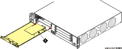
|
|
|