|
|
|
In traditional servers running Avaya MultiVantage Software 1.2, ports are identified by the cabinet number, carrier, slot and port (e.g., 01A0704). This naming convention does not make physical sense for the Media Modules. Therefore a new convention was developed that meets the needs of the G700 Media Gateways, yet for portability to traditional administration maintains the 7 character field. Also, in traditional server administration there are many commands that either require port fields as an argument to the command or require a port field value be entered on the form. Therefore these commands will need to understand Media Module port fields and accept them as valid entries. This applies to both the S8300 Media Server and an external communications controller, whether it be an S8700 Media Server or another server. The media gateway format is GGGVMPP, where GGG is the media-gateway number, VM is the module slot number, and PP is the port number. Note that the V is a required character that is part of the module slot number. The letter 'V' was chosen due to the hardware labeling of the media module slots as V1-V4.
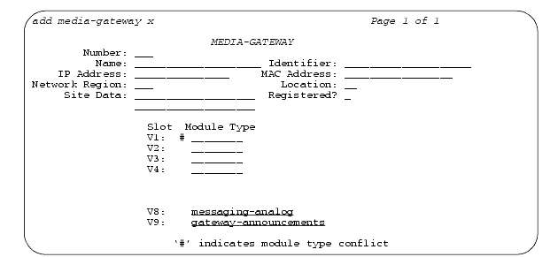
The G700 Media Gateway Primary Server administers the G700 Media Gateways by the command add media-gateway x or add media-gateway next, where x is valid between the range of 1 to the capacity for a given primary server, and next is the next available number to be administered.
The commands change media-gateway x, display media-gateway x , and remove media-gateway x are supported in the same manner as the add media-gateway x command.
The Media Gateway form has five administrable fields for identification:
The 'Registered?' field is one (1) character long for indicating whether a G700 Media Gateway is currently registered with the primary server or not. The 'Registered?' field is a display only field. The valid value that the 'Registered?' field can have is y(es) or n(o).
The Media Gateway form has two additional fields for display purposes only: IP Address and MAC Address.
The IP Address field is a 15 character display only field containing the IP Address of the media gateway. The data in this field is of the form: XXX.XXX.XXX.XXX (where XXX is a decimal value between 000 and 255). The IP address field returns a blank field until the Media Gateway registers for the first time. Once the G700 has registered, that IP address will always be displayed, even if the G700 becomes unregistered, until a G700 with a different IP address is validly registered with the same administered identifier. The populated IP address is persistent over reboots.
The MAC Address field is a 17 character display only field containing the MAC Address of the media gateway. The data in this field is of the form: XX:XX:XX:XX:XX:XX (where XX is a hexadecimal value between 00 and FF). The MAC Address field returns a blank field until the G700 registers for the first time. Once the G700 has registered, that MAC Address will always be displayed, even if the G700 becomes unregistered, until a G700 with a different MAC Address is validly registered with the same administered identifier.
The G700 Media Gateway Media Modules are listed by Slot V1-V4, followed by the input field for 'Module Type'. The Media Modules shall be one of six types: analog, bri, dcp, icc, voip, or ds1 (also referred to as E1/T1). The default for the Module Type field is a blank field.
Note: The S8300 Media Server and LSP are both processor-type Media Modules. From a SAT administration view-point, there is no difference between the S8300 Media Server and LSP; therefore, the designation for both is via icc in the Module Type field.
If an administered Media Module is in conflict with the inserted Media Module, then a pound sign (#) shall be displayed to the left of the 'Module Type' field on the Media Gateway form and the following footnote displayed "'#' indicates module type conflict".
For the listing of 'virtual' media modules, the Slots V8-V9 are listed after Slots V1-V4. The Module Type field associated with slot V8 is an administrable field that only accepts a value of 'messaging-analog'. The Module Type field associated with slot V9 is an administrable field that only accepts a value of 'gateway-announcements'. The default for both is a blank field.
The command enable announcement-board X, where X is the module/board location, adds the specified announcement board to the list of usable announcement boards, as defined in the software, provided there is availability based on the allowable number of announcement boards.
The command disable announcement-board X removes the specified announcement board, whether administered gateway-announcement boards or inserted physical boards, from the list of usable announcement boards, as defined in the software.
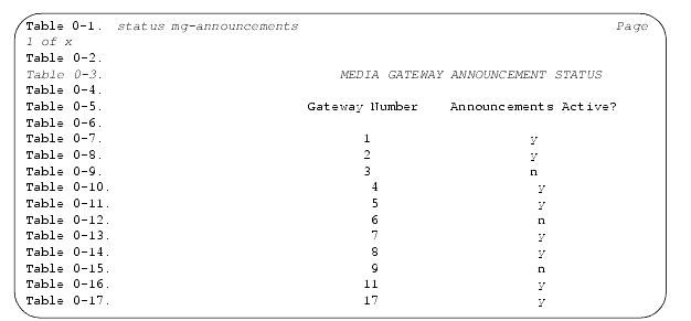
The status mg-announcements command displays the status of the Media Gateway announcements that have been administered. The status indicates whether or not a Media Gateway announcement board is on the list of usable announcement boards as defined in the software.
From the primary server, a command that shows all G700 Media Gateways currently administered is: list media-gateway. Five fields are displayed: number, name, identifier, ip address and registration status:
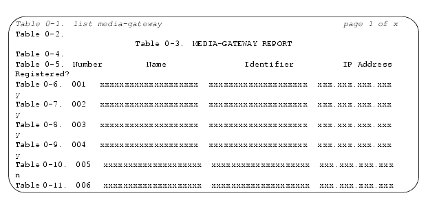
The IP address field returns a blank field until the G700 registers for the first time. Once the G700 has registered, that IP address will always be displayed, even if the G700 becomes unregistered, until a G700 with a different IP address is validly registered with the same administered identifier. The populated IP address is persistent over reboots.
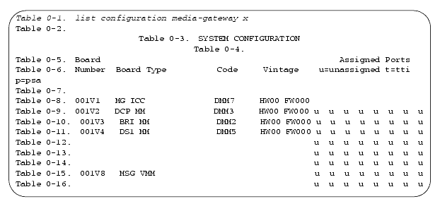
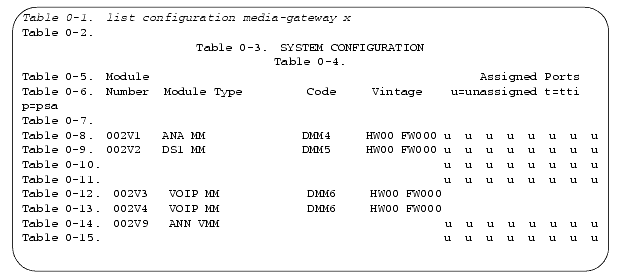
The command list configuration media-gateway x lists all the assigned ports on the Media Modules for the specified Media Gateway. The output from the list configuration media-gateway x command displays a fixed number of assigned ports for each Media Module type: analog(8), dcp(8), bri(8), ds1(32), voip(none) and icc(none).
Note: Those with none as the number of assigned ports display blanks.
The virtual Slot V8, assigned to Analog Messaging, and the virtual Slot V9, assigned to Announcements, display sixteen (16) ports.
Each of the assigned Media Gateway ports are labeled as 'u' for unassigned, 't' for tti, 'p' for psa or a value between 01 and the max number of assigned ports for each Media Module type when that port is assigned.
Module Number displays in the format of GGGVM, where GGG is the G700 number and VM is the module number (V1-V4) or the virtual slots V8 or V9.
Module Types display as 'ANA MM', 'ANN VMM', 'BRI MM', 'DCP MM', 'DS1 MM', 'MG ICC', 'MSG VMM' or 'VOIP MM'.
Code displays as 'DMM2' (for BRI), 'DMM3' (for DCP), 'DMM4' (for Analog), 'DMM5' (for E1/T1), 'DMM6' (for VoIP), or 'DMM7' (for ICC).
Note: No code is listed for the virtual media modules in slots V8 and V9.
Module Vintage are displayed for both the hardware and firmware.
Note: No vintage is listed for the virtual media modules in slots V8 and V9.
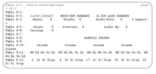
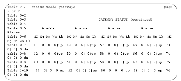
The status media-gateway command displays the alarm status for the administered G700 Media Gateways. This command lists alarms, busyout summary, and H.248 link status for the media gateways. The alarms displayed here are only associated with board type alarms on the Media Modules. Status for VoIP and MGP alarms are provided via the Media Gateway Processor CLI.
There are certain Avaya MultiVantage Software 1.2 SAT commands that have no practical use or are not supported. These commands are removed from the S8300 Media Server/LSP software to prevent any misunderstanding or confusion as to what functions are supported. The S8300 Media Server/LSP has a subset of the MultiVantage software code.
Table 41 through Table 43 can be read by using the column heading followed by the row element (e.g. add atm). Row elements with items in '()' are a third required part of the command (e.g. list configuration atm). The columns of these table are independent of each other. These commands may or may not require an argument. Press help for further instructions about the expected argument type.
|
|
|