

|
|
|
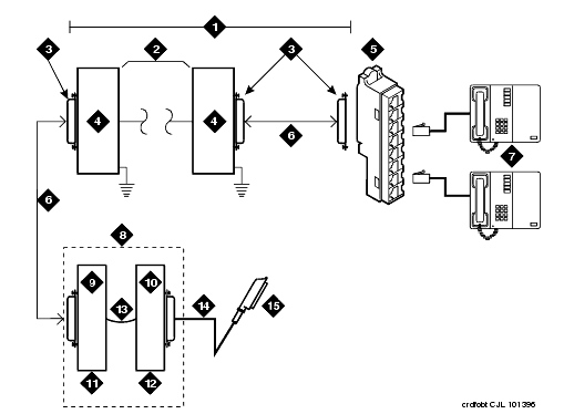
Connections for 1 to 8 Out-of-Building Analog Telephones shows the connections for 1 to 8 off-premises analog telephones.
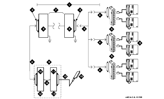
Connections to 24 Out-of-Building Telephones shows the connections for up to 24 off-premises analog telephones. Concentrations of analog line pairs are used at both buildings to minimize the off-premises wiring required. At the MDF, jumpers must be connected between 1 row/connecting block in the white field and up to 3 rows/connecting blocks in the purple field. At the station location, a WP-90929, List 1 Concentrator Cable is used. There are 8 station appearances on each of the 3 fingers of the concentrator cable.
The maximum distance from the media gateway to the out-of-building telephone is 6000 feet (1829 meters) using 24 AWG (#5) (0.5 square millimeters) wire.
The maximum range of out-of-building analog telephones (500-, 2500-, or 7100-types) connected to an analog line circuit pack should be such that the maximum loop resistance does not exceed 1300 ohms.
Connections for 1 to 8 Out-of-Building Analog Telephones���
Connections to 24 Out-of-Building Telephones���
Both building entrances require carbon block or equivalent protection and sneak current protection. Protection can be provided by:
The 4-type protector is the preferred device. For installations not using primary protection, 4-type protectors should always be used. When the 3-type protector is already installed, a separate sneak current protector is required.
The multi-pair protector units and the off-premises cabling must be locally engineered. Connected multi-pair protector units (female 25-pair connector) are recommended. Analog Line Circuit Protectors shows the recommended protectors.
The protectors can be ordered from the Premises Distribution Systems Equipment and Supplies Catalog.
| Primary1 |
Primary (with heat coil) |
Sneak Current Protectors1 |
|---|---|---|
| 3B1A (carbon) |
4B1C (carbon) |
220029 Fuse |
| 3B1E-W (wide gap gas tube) |
4B1E-W (wide gap gas tube) |
SCP-1 |
| 3C1S (solid state) |
4C1S (solid state) |
� |
1The 3-type protectors should be used only if they are already part of the existing protection system. A sneak current protector is always required when a 3-type primary protector is used.
|
Analog telephones connected to TN746B Analog Line circuit packs cannot be installed in an exposed environment.
Digital out-of-building telephones require protection at both building entrances. The 4C3S-75 Enhanced Protector and the ITW Linx Enhanced Protector can be used to protect digital telephones and digital line circuit packs. These units provide primary and sneak current protection. The 4C3S-75 is equipped with a heat coil for sneak current protection, and the ITW Linx is equipped with replaceable fuses for sneak current protection.
NOTE: The TN2181 16-port, 2-wire digital line circuit pack may not be approved for some out-of-building uses. Contact your Avaya representative for more information.
The 4C3S-75 may be used only with TN754B circuit packs circuit packs. Digital Voice Circuit Protectors lists the approved protectors.
When possible, all new and reused wiring installations should use blocks that accept the standard 5-pin plug-in 4C3S-75 protector. However, there are reused wiring installations where this may not be cost effective. For these installations, the ITW Linx protector may be installed.
An example of this is where screw-type carbon block protectors--or other non-plug-compatible types--are in place and it is too costly to reterminate the outside plant cable on a 5-pin mounting block for only a few out-of-building terminals.
The ITW Linx Enhanced Protector can be installed in series with existing primary protection. The ITW Linx Enhanced Protector mounts directly on connecting blocks and requires a separate ground bar.
The 4C3S-75 protector cannot be installed in series with other types of primary protection. It must be installed as the only protection on the line entering the building. For the 4C3S-75 protector there are a variety of 25-, 50-, and 100-pair protector panels equipped with 110-type connecting blocks and/or RJ21X connectors.
The maximum range for out-of-building digital telephones is 3400 feet when using 24 AWG (#5) (0.5�square millimeters) wire and 2200 feet (670 meters) when using 26 AWG (#4) (0.4�square millimeters) wire. The range can be extended to 5000 feet (1524 meters) using 24 AWG (#5) wire or 4000�feet (1220 meters) using 26 AWG (#4) wire with the use of a data link protector. The protector is an isolating transformer used to remove phantom power on the media gateway side and re-introduce it on the terminal side.
When a protector is used, the telephone must be locally powered by an external power supply or through the AC power cord provided with some telephones. The protector is installed on the equipment side of the protection in both buildings.
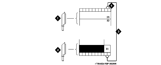
Refer to Example Adjunct Power Connections and Connections at Trunk/Auxiliary Field.
Connections at Trunk/Auxiliary Field
|
|
|