Reliability when sending voice bearer over ATM or CSS
The following are supported with the S8700 Media Server when sending voice bearer over ATM or CSS:
- Duplex reliability
- High reliability
- Critical reliability
Duplex Reliability when sending voice bearer over CSS or ATM
The duplex-reliability option is the most basic option. A duplex-reliability configuration consists of the following:
- Two S8700 Media Servers
- One Ethernet switch
- One UPS unit for each S8700 Media Server. The use of two UPS units ensures that a single UPS failure or repair operation will not disable the system.
- One IPSI in each IPSI-connected port network.
Voice and data bearer traffic between port networks is carried on a simplex network that is made up of one Expansion Interface (EI) in each port network. Avaya offers different types of EI circuit packs, one for CSS, one for ATM. The EIs are cabled with lightguide fiber to either the Center Stage Switch (CSS) or an Asynchronous Transfer Mode (ATM) switch.
See Figure 7, Duplex-reliability configuration when sending voice bearer over CSS or ATM, for an example of a duplex reliability when sending voice bearer over CSS or ATM.
Figure 7: Duplex-reliability configuration when sending voice bearer over CSS or ATM
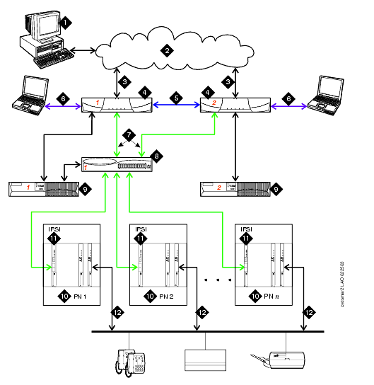
Figure notes
| Number |
Description of the Connection |
-
|
The Administration PC can be used to access the S8700 Media Server over the corporate LAN. |
-
|
Corporate LAN. |
-
|
Corporate LAN interface: default Ethernet 4-- The Ethernet link from the S8700 Media Server to the LAN. Used for administration and can be used for alarming by way of Simple Network Message Protocol (SNMP) traps. The Ethernet connection to the corporate LAN in this figure is a non-dedicated network. IP addresses for the various components of the S8700 Media Server must be administered with care to prevent conflicts with other equipment that shares the LAN. |
-
|
The S8700 Media Servers pair, one server in an active mode and the other server on standby. |
-
|
Duplication links: The Ethernet link, default Ethernet 2, and the fiber link. |
-
|
Services interface: default Ethernet 1-The server's dedicated Ethernet connection from the S8700 Media Server to a laptop. This link is active only during on-site administration or onsite maintenance. |
-
|
Network control A interface: default Ethernet 0-The server's Ethernet connection to one or two Ethernet switches. This private LAN carries the control signals for the PNs. |
-
|
Ethernet switch -- at least one Ethernet switch is required to support the S8700 Media Server's control network. If many PNs are present, two Ethernet switches may be daisy-chained together to provide sufficient Ethernet connections to the IPSI boards in the PNs. |
-
|
UPS -- Keeps the S8700 Media Servers and Ethernet switches functional during brief power outages. |
-
|
PN -- Provides the telecommunications functions of the S8700 Media Server. |
-
|
IPSI -- The IPSI circuit pack carries the control network signals to the PNs and provides tone clock functionality. |
-
|
Bearer connectivity |
High Reliability when sending voice bearer over CSS or ATM
The high-reliability configuration option builds on the duplex-reliability option. The high-reliability duplicates components so that no single point of failure exists in the control network. The high-reliability configuration consists of the following:
- Two S8700 Media Servers
- Two Ethernet switches
- Two UPS units
- Two IPSI circuit packs in each IPSI-connected port network
Voice and data bearer traffic between port networks is carried on a simplex network that is made up of one Expansion Interface (EI) in each port network. Avaya offers different types of EI circuit packs, one for CSS, one for ATM. The EIs are cabled with lightguide fiber to either the Center Stage Switch (CSS) or an Asynchronous Transfer Mode (ATM) switch.
See Figure 8, High- or critical-reliability configuration when sending voice bearer over CSS or ATM, for an example of a high-reliability configuration when sending voice bearer over CSS or ATM.
Figure 8: High- or critical-reliability configuration when sending voice bearer over CSS or ATM
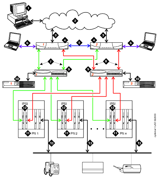
Figure notes
| Number |
Description of Connection |
-
|
Administration PC -- Used to access S8700 Media Server over the corporate LAN. |
-
|
Corporate LAN. |
-
|
Corporate LAN interface: default Ethernet 4 --The Ethernet link from the S8700 Media Server to the LAN. Used for administration and can be used for alarming by way of the Simple Network Message Protocol (SNMP) traps. |
-
|
S8700 Media Server -- Two are always present. One in active mode and the other on standby. |
-
|
Duplication Links: The Ethernet link, default Ethernet 2, and the fiber link. |
-
|
Services interface: default Ethernet 1-The server's dedicated Ethernet connection from the S8700 Media Server to a Services laptop. This link is active only during onsite administration or onsite maintenance. |
-
|
Network control A interface: default Ethernet 0-The server's Ethernet connection to one or two Ethernet switches. This private LAN carries the control signals for the PNs when possible. Control network A is considered the primary control network because it connects to the primary IPSI board in a PN. |
-
|
Network control B interface: default Ethernet 3-The S8700 Media Server's Ethernet connection to a duplicated set of Ethernet switches. This private LAN carries control signals for the PNs when the primary control network is unavailable. Control network B connects to the secondary IPSI board in a PN. When the problem is resolved, primary control is returned to control network A. |
-
|
Ethernet switch -- At least one is required to support each control network. |
-
|
UPS -- Keeps the S8700 Media Servers and Ethernet switches functional during brief power outages. Usually, UPS one powers server one and the Ethernet switch associated with it. UPS two powers server two and the Ethernet switch associated with it. |
-
|
PN -- Provides the telecommunications functions of the S8700 Media Server. For high reliability, each IPSI-connected PN contains a pair of IPSI circuit packs. This pair consists of, one primary circuit pack, and a duplicate secondary circuit pack as a backup. For critical reliability, the bearer network, among the port networks is also duplicated. Two EI circuit packs or two ATM circuit packs are present in each PN instead of just one. |
-
|
IPSI -- The IPSI circuit pack is duplicated in every IPSI-connected PN in a high- or critical-reliability configuration. The secondary IPSI is connected to control network B. The secondary IPSI takes over in case of problems with the primary control network. The S8700 Media Server regularly tests the duplicated IPSI to make sure it is ready for service. |
-
|
Bearer Connectivity |
Critical Reliability when sending voice bearer over CSS or ATM
The critical-reliability configuration option is similar to the high-reliability configuration option. In addition, the critical-reliability configuration duplicates the bearer network channels among the PNs. Like the high-reliability configuration, the critical-reliability configuration consists of the following:
- Two S8700 Media Servers
- Two Ethernet switches
- Two UPS units
- Two IPSI circuit packs in each IPSI-connected port network
Voice and data bearer traffic between port networks is carried on a duplex network that is made up of two Expansion Interface (EI) in each port network. The EIs are cabled with lightguide fiber to either a duplicated Center Stage Switch (CSS) or a duplicated Asynchronous Transfer Mode (ATM) switch.
See Figure 8, High- or critical-reliability configuration when sending voice bearer over CSS or ATM, for an example of a critical-reliability configuration when sending voice bearer over CSS or ATM.

