DS1C Converter Complex Administration for TN574 Circuit Packs
Return to Task List
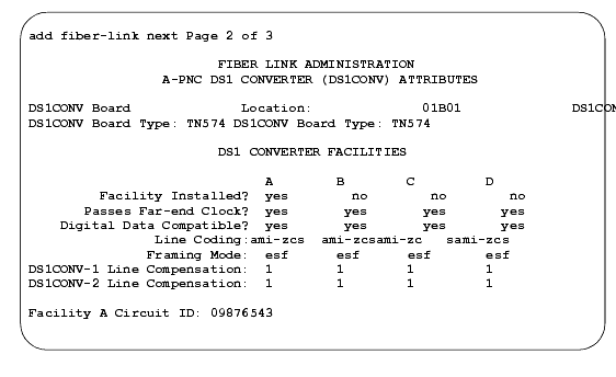
Fiber Link Administration form for TN574 Circuit Pack (DS1 Converter Complex Administration) (page 2 of 3) shows the fields available to administer the TN574 circuit pack.
The following DS1 Converter Complex fields appear on Page 2 when the
Is one endpoint remoted via a DS1 Converter Complex? field is
y.
-
DS1CONV Board Location
-- Enter the cabinet, carrier, and slot that identifies the physical location of the converter circuit pack connected to the first endpoint of the fiber link. This is entered on Page 1 and displays on Page 2.
-
DS1CONV Board Type
-- Display-only field showing the type of DS1 Converter circuit pack for the first endpoint.
-
DS1CONV Board Location
-- Enter the cabinet, carrier, and slot that identifies the physical location of the converter circuit pack connected to the second endpoint of the fiber link.
-
DS1CONV Board Type
-- Display-only field showing the type of DS1 Converter circuit pack for the second endpoint. This field is updated via the Change Circuit-packs command.
-
Facility Installed
-- Enter
yes in the B, C, and D columns under the DS1 Converter Facilities heading to indicate that this DS1 facility is physically installed. At least facility A must be installed within the converter complex. Default is
yes for Facility A.
-
Passes Far-end Clock
-- Enter
yes in the B, C, and D columns under the DS1 Converter Facilities heading to indicate that this DS1 facility is suitable to be used as a clock source. If the DS1 signal does not come directly from the far end converter circuit pack or the network (such as when the signal is converted from digital to analog and then back to digital), enter
no. Default is
yes for Facility A.
This field determines whether the DS1 converter circuit pack can use receive DS1 signal timing to time the transmit fiber signal. This is necessary for passing timing from a master PN to a slave PN across a Converter Complex.
-
Digital Data Compatible
-- Enter
yes (default) in the B, C, and D columns under the DS1 Converter Facilities heading to indicate that this DS1 facility is suitable for transmission of digital data. At least Facility A must be suitable for transmission of digital data. If Customer Premises Equipment that alters digital data exists on this facility (such as with a channel expansion multiplexer), enter
no.
-
Line Coding
-- Enter the line coding format,
ami-zcs (default), or
ami-basic,
b8zs, or
hdb3 in the A, B, C, and D columns under the DS1 Converter Facilities heading for each DS1 facility.
When ami-zcs line coding is used, all-zero bytes are prevented from being transmitted on the DS1 facility because a 1 is arbitrarily written into the second position of each byte. Thus, if no measures are taken to prevent it, ami-zcs line coding results in data corruption. The DS1CONV circuit pack protects the packet facility (one of up to four facilities dynamically allocated by the DS1CONV circuit pack) from corruption through a special escape mechanism.
When b8zs line coding is used, it maintains DS1 facility's ones-density requirements by encoding a zero data byte into a specific unique pattern of bipolar violations on the DS1 line. The opposite end recognizes this pattern and replaces it with a zero data byte when the data is recovered at the receiving end.
-
DS1CONV-1 Line Compensation -- Enter the line compensation (
1 to
5) in the A, B, C, and D columns under the DS1 Converter Facilities heading for each DS1 facility connected to ENDPOINT-1 (see Distance to DSX-1 Interface (feet)).
The DS1 line signal is pre-equalized at the transmitter so that DS1 line pulses are the correct amplitude and shape when they reach the Network Interface. The amount of equalization necessary is determined by the distance to the Network Interface (when the endpoint supplies a DSX-1 interface) and also by the type of wiring used to connect to the Network Interface. The types of wiring allowed are 22-gauge ABAM (shielded twisted pair) cable, 24-gauge Premises Distribution System (PDS) wiring, and 26-gauge PDS wiring.
-
DS1CONV-2 Line Compensation
-- Enter the line compensation (
1 to
5) in the A, B, C, and D columns under the DS1 Converter Facilities heading for each DS1 facility connected to ENDPOINT-2 (see Distance to DSX-1 Interface (feet). The DS1 line signal is pre-equalized at the transmitter so that DS1 line pulses are the correct amplitude and shape when they reach the Network Interface. The amount of equalization necessary is determined by the distance to the Network Interface (when the endpoint supplies a DSX-1 interface) and also by the type of wiring used to connect to the Network Interface. The types of wiring allowed are 22-gauge ABAM (shielded twisted pair) cable, 24-gauge Premises Distribution System (PDS) wiring, and 26-gauge PDS wiring.
-
Facility A Circuit ID
-- Displays when the value in
Facility Installed for Facility A is
yes. Enter up to 40 characters to identify the cabinet, carrier, and slot of the DS1 Converter circuit pack's physical location.
Similarly, Facility B Circuit ID, Facility C Circuit ID, and Facility D Circuit ID fields display for each of the DS1 Converter Facilities when
yes is entered in the corresponding Facility Installed field.
Fiber Link Administration form for TN574 Circuit Pack (DS1 Converter Complex Administration) (page 2 of 3)

