DEFINITY Made Easy Home Page Table of contents Previous page Next page Index Links Frequently asked questions
Go to Upgrades for si Go to Installation for MCC Go to Installation for SCC


Install Rectifier Modules and Battery Interface Unit

Return to Task List

Each rectifier module operates as an integral part of a complete power system with battery backup. The modules operate in a redundant, high reliability mode to provide -48 VDC at 850 Watts to a common power bus.

The Battery Interface Unit (BIU) controls the rectifier modules, manages the batteries, and reports the status of system power. The BIU provides the Remote Power Off (RPO) option and battery alarm interfaces for internal and external alarms.

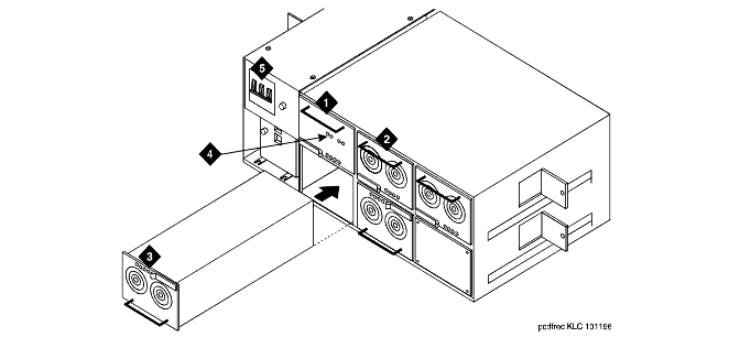
  1. Install the BU3200A Battery Interface Unit in the first slot of the power distribution unit. See Rectifier Module Installation.

Note: The BIU and the rectifier modules are keyed and can only install 1 way.

  1. Install the first 2 RM0850HA100 Rectifier Modules into the second and third slots of the power distribution unit.

  2. If 2 to 3 carriers are installed in the system, install a third rectifier module (N+1).

  3. If 4 to 5 carriers are installed in the system, install a fourth rectifier module.

  4. The fifth rectifier module slot is reserved for future system growth.

Rectifier Module Installation

Figure Notes:
      1. Install Battery Interface Unit into Slot 1

      2. Install Rectifier Modules into Slots 2-5

      3. Rectifier Module 3 (in Slot 4)

      4. Test Points

      5. Main Circuit Breakers

Return to Task List


DEFINITY Made Easy Home Page Table of contents Previous page Next page Index Links Frequently asked questions
Go to Upgrades for si Go to Installation for MCC Go to Installation for SCC
Copyright 2001 Avaya Inc.
Send comments to MadeEasy Development Team


Always check at the Made Easy Web site for the most current information.