Station Wiring Design
The following hardware and cabling is used:
A brief description of each of the above listed items follows. Ordering information is not provided for station cables and information outlets.
Information Outlets
Information outlets are 8-pin modular wall jacks. Most of the outlets are wired with push-on connections. Information outlets are also available that connect to a double modular plug-ended 4-pair station cable routed from the MDF, a site/satellite location, or an adapter.
Station Cables
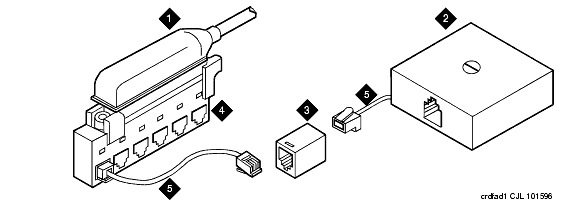
For clarity, a station cable is either a 25-pair cable, multiple 25-pair cable, or 4-pair D-inside wire (DIW) run from the equipment room, site/satellite location, or adapter to the information outlets. The following station cables are available. See Example of Extending 4-Pair Station Cables.
25-pair station cable
-- Use between the equipment room and site/ satellite locations or adapters. Use an A25D cable (male to male) between the equipment room and satellite closet. Use a B25A cable between the equipment room and site closet or adapter.
Multiple 25-pair station cable
-- Use between the equipment room and site/satellite locations or adapters. This cable consists of individually sheathed 25-pair cables with a factory-installed 25-pair connector on each end. Use a male to female cable to connect between the equipment room and site location or adapter. Use a male to male cable to connect between the equipment room and satellite location. Staggered-finger cables are recommended for all multiple 25-pair station cables and are available in both double-ended and single-ended types.
Single modular plug-ended 4-pair station cable
-- Use this cable between adapters and information outlets that require push-on connections. It can also be used when 4-pair station cables are field- terminated on the 110-type terminal blocks in the equipment room or satellite closet and modularly connected to information outlets. The station cables are available in the following lengths:
- 10 ft (3.05 m)
- 25 ft (7.62 m)
- 50 ft (15.24 m)
- 75 ft (22.86 m)
- 100 ft (30.5 m)
- 150 ft (45.72 m)
- 200 ft (61 m)
Double modular plug-ended 4-pair station cable
-- Use this cable to provide nonstandard length runs between adapters and information outlets with push-on connections. It can also be used between adapters and modularly connected information outlets. It is available in the same lengths as the single modular plug-ended cable.
Bulk Cable
-- Same as the 25-pair cable or multiple 25-pair cable; however, the bulk cable is not equipped with connectors. Use this cable between the equipment room and satellite closets when both are equipped with punch-down type terminal/connecting blocks.
4-pair station cable
-- Use this cable when 4-pair station cables are to be field-terminated on the 110-type terminal blocks in the equipment room or satellite closet and the information outlets require push-on connections
Closets
Site Locations
Site locations are closets that provide a point in the station wiring for the administration of remote powering. Adapters are used at site locations to terminate the 25-pair station cables and provide connection points (modular jacks) for power adapters and 4-pair station cables.
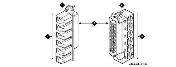
The258A and BR2580A adapters plug into a 25-pair female cable connector. These adapters divide the 25-pair cable into six 4-pair (modular jack) circuits. See 258A and BR2580A Adapters.
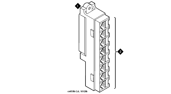
The 356A adapter plugs into a 25-pair female cable connector. See 356A Adapter. The 356A adapter divides the 25-pair cable into eight 3-pair circuits. Although the circuits are 3-pair, the adapters modular jacks will accept the 8-wide modular plug used on the 4-pair station cable.
Use theZD8AJ adapter to connect a Multi-button Electronic Telephone (MET) line cord to an information outlet. The adapter interchanges pairs 3 and 4 to correspond with the pair assignments for the telephone. The line cord plugs into the adapter, and then the adapter plugs into an information outlet.
Satellite Locations
Satellite locations are closets that provide an administration point (using cross-connect equipment) for station cables and where adjunct power may be applied. The station cable circuits from the equipment room MDF are 3-pair. At the satellite location, 4-pair circuits run to the information outlets. The hardware used is 110-type terminal blocks.
Satellite Locations Using 110-Type Hardware
Each terminal block has a 3-pair (white field) and a 4-pair (blue field) located on the same terminal block.
The 110A-type terminal block that can be used is the 110AE1-75FT. It must be field-terminated to both the white and blue fields.
The 300-pair 110P-type terminal blocks that can be used are:
- 110PE1-300CT/FT
-- 25-pair connector on the white field and field-terminated on the blue field
- 110PE1-300FT
-- Field-terminated on both the white and blue fields
The 900-pair 110P-type terminal blocks that can be used are:
- 110PE1-900CT/FT
-- 25-pair connector on the white field and field-terminated on the blue field
- 110PE1-900FT
-- Field-terminated on both the white and blue fields
Example of Extending 4-Pair Station Cables

Figure Notes:
- Station Cable
- Information Outlet
- 451A In-Line Adapter
- 258A Adapter
- 4-Pair Station Cable
258A and BR2580A Adapters

Figure Notes:
- BR2580A Adapter
- 258A Adapter
- 25-Pair Male Ribbon Connector
- 4-Pair Modular Jacks (8 Pins)
356A Adapter

Figure Notes:
- 356A Adapter
- 4-Pair Modular Jacks (6 pins each, connected to 25-pair ribbon connector)


