DEFINITY Made Easy Home Page Table of contents Previous page Next page Index Links Frequently asked questions
Go to Upgrades for si Go to Installation for MCC Go to Installation for SCC


Station Circuit Distribution from Equipment Room

This section explains the station circuit distribution from the equipment room to the information outlets for new wiring installations. Example connection diagrams are provided to show the options for running and connecting the station cables.

If most of the telephones/voice terminals that require remote powering are within 250 ft (76.2 m) of the equipment room, 4-pair station circuits are run from the equipment room to the information outlets. If this is not the case, or if the customer requires 2-point administration, 3-pair station circuits are run from the equipment room to satellite locations. Then, the 4-pair station circuits are run from the satellite locations to the information outlets.

This section has information about

Lists of terminals that can be connected to the system are provided in

4-Pair Station Circuits

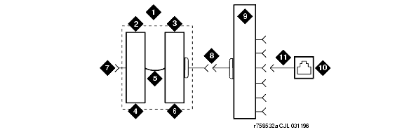
Four-pair circuits can be run directly from an equipment room MDF to a 258A or BR2580A adapter as shown in 4-Pair Circuit Distribution and Connectivity. The 4-pair station cables connect the adapter to the information outlets.

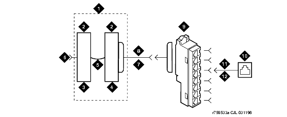
The 4-pair station cables can be run directly from the equipment room to the information outlets if 4-pair terminal blocks are used in the distribution field. See 4-Pair Run to Equipment Room or Satellite Location. The station cables must be field-terminated on the 110-type terminal blocks.

If 110-type terminal blocks are used with a modular plug-ended station cable, an adapter can be connected directly to the 110-type terminal block connectors. See 4-Pair Run to Equipment Room or Satellite Location.

3-Pair to 4-Pair Station Circuit Distribution

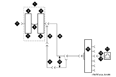
3-Pair to 4-Pair Satellite Location Connectivity shows the 3-pair circuit distribution from an equipment room MDF to a satellite location using 110-type hardware. Four-pair circuits are distributed from the satellite location to the information outlets.

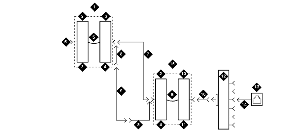
Three-pair circuits can also be run directly from the equipment room MDF to a 356A adapter as shown in 3-Pair to 4-Pair Circuit Distribution and Connectivity. Four-pair station cables connect the adapter to the information outlets. Four-pair station cables can be run directly from a satellite location to the information outlets as previously described.


Note: Bridged taps are not allowed on any part of the station wiring.

4-Pair Circuit Distribution and Connectivity

Figure Notes:
      1. Part of Main Distribution Frame (MDF)

      2. 3-Pair Connecting Blocks

      3. 4-Pair Connecting Blocks

      4. Purple Field

      5. Blue Field

      6. Patch Cord or Cross-Connect Jumpers

      7. To System Cabinet (Three-Pair Modularity)

      8. B25A Cable

      9. Connectorized (Staggered Finger) Multiple 25-Pair Cable

      10. 258A or BR2580A Adapter

      11. Information Outlet

      12. 4-Pair Circuit

      13. DIW Station Cable (D-Inside Wire)

4-Pair Run to Equipment Room or Satellite Location

Figure Notes:
      1. Station Side of MDF or Satellite Location

      2. 4-Pair Circuit

      3. Blue Field

      4. DIW Station Cable (D-Inside Wire)

      5. Information Outlet

4-Pair Run to Equipment Room or Satellite Location

Figure Notes:
      1. Part of MDF

      2. 3-Pair Connecting Blocks

      3. 4-Pair Connecting Blocks

      4. Purple Field

      5. Patch Cord or Cross-Connect Jumpers

      6. Blue Field

      7. To System Cabinet (3 pair modularity)

      8. A25D Cable

      9. 258A or BR2580A Adapter

      10. Information Outlet

      11. 4-Pair Circuit (DIW station cable (D-Inside Wire))

3-Pair to 4-Pair Satellite Location Connectivity

Figure Notes:
      1. Part of MDF

      2. 3-Pair Connecting Blocks

      3. Purple Field

      4. White Field

      5. Patch Cord or Cross-Connect Jumpers

      6. To System Cabinet (3 Pair Modularity)

      7. A25D Cable (3-Pair Circuits)

      8. B25A Cable

      9. Connectorized (staggered finger) Multiple 25-Pair Cable

      10. 4-Pair Connecting Blocks

      11. Blue Field

      12. 258A or BR2580A Adapter

      13. Information Outlet

      14. 4-Pair Circuit [DIW Station Cable (D-Inside Wire)]

      15. Part of Satellite Location

      16. 4-Pair Circuits (B25A Cable)

3-Pair to 4-Pair Circuit Distribution and Connectivity

Figure Notes:
      1. Part of Main Distribution Frame (MDF)

      2. 3-Pair Connecting Blocks

      3. Purple Field

      4. Blue Field

      5. Patch Cord or Cross-Connect Jumpers

      6. To System Cabinet (3-Pair Modularity)

      7. B25A Cable

      8. 3-Pair Circuits

      9. 356A Adapter

      10. Information Outlet

      11. 3-Pair Circuit in 4-Pair Wire

      12. DIW Station Cable (D-Inside Wire)


DEFINITY Made Easy Home Page Table of contents Previous page Next page Index Links Frequently asked questions
Go to Upgrades for si Go to Installation for MCC Go to Installation for SCC
Copyright 2001 Avaya Inc.
Send comments to MadeEasy Development Team


Always check at the Made Easy Web site for the most current information.