DEFINITY Made Easy Tools
Issue 3, December 2001
Installing the Stratum 3 Clock
Cable the Stratum 3 Clock
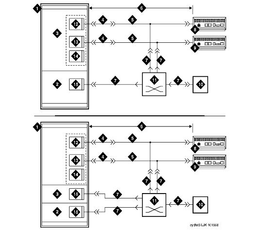
Typical Connections to Stratum 3 Clock shows typical connections to a Stratum 3 Clock cabinet. Connections are made through the yellow field cross-connect. A custom "Y" cable (H600-274) connects the CSU to the DS1 circuit pack and taps off the input for the Stratum 3 Clock. A resistor built into the cable to provides the necessary isolation between the system and the clock. The "Y" cable plugs directly into the CSU and connects to standard cables for interface to the system and the yellow field on the MDF.
The H600-307 cable connects the system end of the "Y" cable to a DS1 circuit pack (shown as TN464/2464, TN722, or TN767). The B25A cable connects the clock end of the "Y" cable to the yellow field on the MDF.
Typical Connections to Stratum 3 Clock
Figure Notes:
- SCC Cabinet (PPN)
- "A" Position
- "B" Position
- H600-307 Cable
- H600-247 G2 Cable
- 1300 Feet (396 m)
- B25A (Male-to-Female) Cable
- Channel Service Unit (Secondary)
- Channel Service Unit (Primary)
- Stratum 3 Clock
- Main Distribution Frame (MDF)
- DS1/E1 Interface Circuit Pack
- DS1 Tie Trunk Circuit Pack
- DS1 Interface Circuit Pack
- Tone-Clock Circuit Pack
| Copyright� 2001 Avaya Inc. |
| Send comments to MadeEasy Development Team |
| Always check at the Made Easy Web site for the most current information. |
