DEFINITY Made Easy Tools
Issue 3, December 2001
Install and Wire Telephones
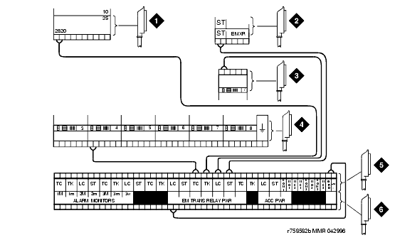
Install Telephones Used for Emergency Transfer and as Normal Extension (Trunk/Auxiliary Field)
- Connect a pair of wires between the -48V and GRD terminals on the yellow emergency transfer row/connecting block to the EM TRANS RELAY PWR terminal. See Connections for Telephone Used for Emergency Transfer and as Normal Extension.
- Connect CO trunk leads from the purple field to TC terminals on the yellow emergency transfer row/connecting block for each trunk.
- Connect CO trunk leads from the green field to TK terminals on the yellow emergency transfer row/connecting block for each trunk.
- Connect telephone leads from the purple analog line circuit pack row/ connecting block to the LC terminals on the yellow emergency transfer row/connecting block for each telephone.
- Connect ST leads on the yellow emergency transfer row/connecting block for each emergency transfer telephone to the assigned terminal in the blue or white station distribution field.
- Install the telephone:
Connections for Telephone Used for Emergency Transfer and as Normal Extension
Figure Notes:
| Copyright� 2001 Avaya Inc. |
| Send comments to MadeEasy Development Team |
| Always check at the Made Easy Web site for the most current information. |
