DEFINITY Made Easy Home Page Table of contents Previous page Next page Index Links Frequently asked questions
Go to Upgrades for si Go to Installation for MCC Go to Installation for SCC


Data Module Option Switch Settings

Return to Task List

This section contains information

Task List: Data Module Switches and Options

About DCS Switch Settings

The Distributed Communications System (DCS) for a system is sometimes connected to the system through the Processor Interface circuit pack or a Network Control/Packet Interface (Net/Pkt) circuit pack. The first circuit can be connected directly to the DCS through the processor interface (PI) connector on the rear of the control carrier.

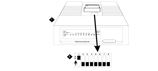
Any of the remaining three circuits on the processor interface used to support the Distributed Communications System (DCS) must be connected through a data module serving as the interface link. The option settings for a 7400A Data Module are shown in Data Module Option Switch Settings. Refer to Data Module DIP Switch Locations: for the location of the switches.
.

Data Module Option Switch Settings

DIP Switch
Function
Setting

1

With Phone
Without Phone

ON
OFF

5

Data Metering
No Data Metering

ON
OFF

8

Make Busy on Loc Loop
No Make Busy on Loc Loop

ON
OFF

2, 3, 4, 6, and 7


OFF

Data Module DIP Switch Locations:

Figure Notes:
      1. Data Module (7400A Shown)

      2. DIP Switch

About 7400D Data Module Option Settings

The option settings shown in 7400 Series Data Module Options (Answer Only Interface) are for the Answer Only interface and are set from the front panel interface. Set only the desired speed of the 7400D. All other default settings can be used.

7400 Series Data Module Options (Answer Only Interface)

Set Option Display
Abbreviation
Possible Values
Default

Set 300 SPEED?

300

ON, OFF

ON

Set 1200 SPEED?

1200

ON, OFF

ON

Set 2400 SPEED?

2400

ON, OFF

ON

Set 4800 SPEED?

4800

ON, OFF

ON

Set 9600 SPEED?

9600

ON, OFF

ON

Set 19200 SPEED?

19200

ON, OFF

ON

Set ANSWER?

ANS

AUTO, MANUAL

AUTO

Set CI LEAD?

CI

ON, OFF

OFF (See Note)

Set CH LEAD?

CH

ON, OFF

OFF (See Note)

Set CTS LEAD?

CTS

NORMAL, ON

ON

Set DCD LEAD?

DCD

NORMAL, ON

ON (See Note)

Set DSR LEAD?

DSR

NORMAL, ON

ON (See Note)

Set DTR DETECT?

DTR

0, 10, 20, 30, 50, 100 MSEC

50

Set DTR LEAD?

DTR

EIA STANDARD, IGNORE

EIA STANDARD

Set LL LEAD?

LL

ON, OFF

OFF

Set REMOTE LOOP?

REMLOOP

GRANT, DENY

GRANT

Set RI LEAD?

RI

CYCLE, ON

ON

Set RL LEAD?

RL

ON, OFF

OFF

Set SIGLS DISC?

SIGLS DISC

ON, OFF

ON

Set TIMING?

TIMING

INTERNAL, EXTERNAL

INT

Set TM LEAD?

TM

ON, OFF

OFF


Note: It is recommended that CI and CH be set to ON, and DCD and DSR be set to NORMAL. This allows login information to be displayed on the screen without having to send a carriage return character.

Return to Task List


DEFINITY Made Easy Home Page Table of contents Previous page Next page Index Links Frequently asked questions
Go to Upgrades for si Go to Installation for MCC Go to Installation for SCC
Copyright 2001 Avaya Inc.
Send comments to MadeEasy Development Team


Always check at the Made Easy Web site for the most current information.