DEFINITY Made Easy Tools
Issue 3, December 2001
Test the System
LED Indicators
Refer to the DEFINITY Enterprise Communications Server Maintenance documentation for detailed alarm and LED descriptions. If a maintenance object begins to fail some periodic tests, the system generates an alarm. The system identifies 3 levels of alarms:
- Major Alarms -- Failures that cause critical degradation of service and require immediate attention.
- Minor Alarms -- Failures that cause some degradation of service, but do not cause a critical portion of the system to be inoperable. This condition requires action, but its consequences are not immediate. Problems might be impaired service to a few trunks or stations or interfering with one feature across the entire system.
- Warning Alarms -- Failures that cause no significant degradation of service or failures in equipment external to the system. Warning alarms are not reported to the attendant console or INADS.
Alarms are communicated to the system users and technicians by entries in the alarm log and the lighting of LEDs located on the attendant console, on all circuit packs, and, optionally, on customer-designated voice terminals.
More detailed information is available here for:
- Attendant Console LEDs
- Terminal Alarm NotificationCircuit Pack LEDs
- Circuit Pack LEDs
- DS1 Converter Circuit Pack LEDs
- SPAN LEDs
- LEDS on Standby Components
Attendant Console LEDs
The console has 2 red LEDs, labeled "ALM" and "ACK". The ALM LED lights steadily when there is a major or minor alarm at the system cabinet. The ACK LED lights steadily if the alarm has been successfully reported to INADS. If the system is unable to report the alarm to INADS, the LED flashes; this signals the attendant to call INADS and report the alarm.
Terminal Alarm Notification
Terminal Alarm Notification is an optional feature that displays several types of alarms on voice terminals with administered feature buttons or the attendant console. A maximum of 10 digital and/or hybrid voice terminals may be used.
When an alarm occurs, the green status LED associated with the assigned button is in a steady state. The LED may be turned off by pressing the button associated with the LED. If the LED is off and the alarm has not been resolved by the time maintenance reschedules testing, the green status LED resumes its steady state.
Circuit Pack LEDs
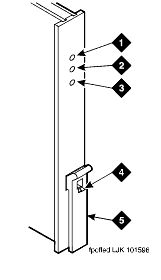
Typically, each circuit pack has 3 LEDs on the front panel. The Circuit Pack LEDs table describes the red, green, and yellow LEDs and their meaning. Also see Circuit Pack LEDs on Faceplate.
DS1 Converter Circuit Pack LEDs
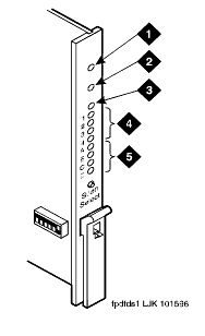
Eleven LEDs provide an indication of the state of the TN1654 DS1 Converter Circuit Pack LEDs and the T1/E1 facilities. The top group has the standard red, green and yellow LEDs. The red LED indicates an alarm condition and the green LED indicates testing in progress. The 4 SPAN LEDs indicate the status of the T1/E1 facilities. The four STATUS LEDs are currently unused and remain off.
The yellow LED is used to indicate the state of the fiber interface, the fiber channel, the control channel, and the communications link to the SPE in the following manner and order of priority. See DS1 Converter Yellow LED Flashing States
SPAN LEDs
The 4 SPAN LEDs indicate the status of the 4 T1/E1 facilities. A SPAN LED is in one of the following states:
- Solid on yellow: Facility is operational and alarm free.
- Blinking yellow for 2 seconds, off 0.1 seconds: Facility is operational and alarm free AND is carrying the control channel (facility A or B only).
- Solid on red: Facility is alarmed.
- Solid off: Facility is not administered or has been busied out.
LEDS on Standby Components
In high and critical reliability systems, duplicated components on standby usually have the yellow LEDs off, with the following exceptions:
- The major, minor and warning alarm LEDs on the SYSAM circuit pack on the standby SPE do not give reliable indications. Note only LEDs on the active SYSAM circuit pack.
- The yellow LED blinks on and off when the standby processor circuit pack is up and standby maintenance is running.
- In high reliability systems with a Center Stage Switch, (duplicated SPE, simplex PNC), the standby Switch Node clock's yellow LED is off. In critical reliability systems, the standby SNC is located on a separate carrier and normally remains lit.
- Yellow LEDs on power units on standby carriers normally remain lit.

