- Fasten the carrier into position with 4 self-tapping screws saved from the removal of the old carrier.
- Connect the P2 and P1 (large and small) connectors to the rear of A carrier. If necessary, to get enough slack in the cables, cut the tie wrap holding the intercabinet cable from the upright in the area of the carrier being installed. Snap the connector lock into place to ensure connection is properly made.
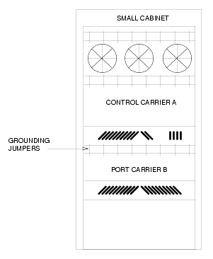
- Connect the 8 ground straps from the B carrier to the new A carrier (see Locations of grounding jumpers). These straps were left connected to the B carrier when the old A carrier was removed.
- For the AC-powered control carrier, install the 2 new carrier-ground straps. One strap connects ground point 1 to the A-carrier frame (on the right side), and the other connects ground point 8 to the A-carrier frame (on the left side).
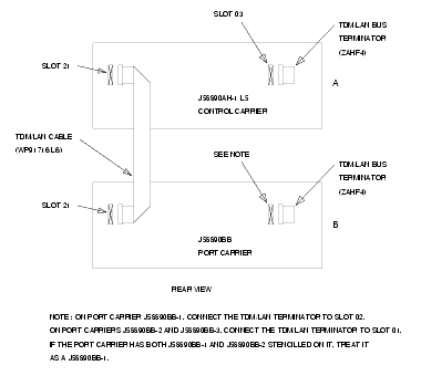
- Connect the new TDM/LAN cable (WP-91716 L6) between the A and B carriers (see TDM/LAN connections for R7si/R8si PPN and the TDM/LAN connections table). The cable is connected to the A and B carriers at the pin-field blocks marked on the left side of each carrier.
- Replace the existing bus terminators (AHF1) with the new ZAHF4 bus terminators. (See TDM/LAN connections for R7si/R8si PPN and the TDM/LAN connections table).
- Install the front trim plates on the A carrier. Install the fan trim plate.
- Peel the old decal strip (designation strip) from the trim plates. Then install the new decal strip at the bottom of the trim panel.
- Install the connector-panel decal on the rear connector panel.
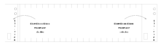
- Install the 631-type power units into the A carrier. Install the new 631DB1 in the right side of the carrier, and reuse the old 631-type power supply in the left side. Do not interchange the units. The 631AR, 631WA1, or 631DA1 is installed in the left side, while the new 631DB1 is installed in the right side (see Locations of power units).
- If the system is equipped with neon message waiting, install the previously removed TN752 or TN755 power unit in port slots 12 and 13 of the carrier (adjacent to the 631DB1).
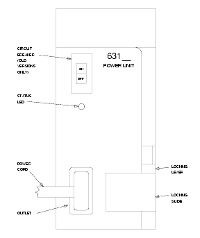
- Connect the power cords to the power units. The power cords are the white cables equipped with plugs that are run through the slots in the front of each carrier (see 631-type power unit).
Locations of grounding jumpers
TDM/LAN connections for R7si/R8si PPN