DEFINITY Made Easy Tools
Issue 3, December 2001
Install Telecommunications Cabling
Connect Trunk Pairs to Cabinet Using Jumper Wires To Establish 3-Pair Modularity
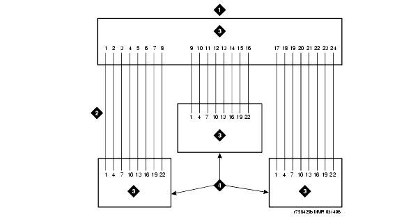
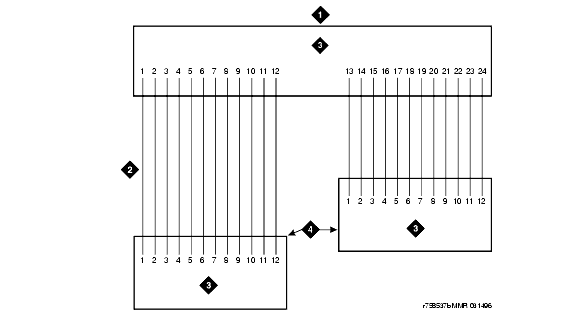
3-Pair Modularity for Trunk Pairs for 1-Pair Trunks and 3-Pair Modularity for Trunk Pairs for 3-Pair Tie Trunks show trunk pairs connected to the cabinet with jumper wires to establish 3-pair modularity.
To connect the trunk pairs to the purple field:
- Connect B25A cables between the network interface and the sneak fuse panels. See 3-Pair Modularity for Trunk Pairs for 1-Pair Trunks.
- Connect A25D/B25A cables from the sneak fuse panels to the 110-type terminal block-type connecting block connectors in the green field.
- Connect 1-pair patch cords/jumper wires from each 110-type terminal block row in the green field to the 110-type terminal block rows in the purple field for 1-pair Central Office (CO) trunks or in 3-Pair Modularity for Trunk Pairs for 3-Pair Tie Trunks for 3-pair tie trunks.
3-Pair Modularity for Trunk Pairs for 1-Pair Trunks
Figure Notes:
3-Pair Modularity for Trunk Pairs for 3-Pair Tie Trunks
Figure Notes:
| Copyright� 2001 Avaya Inc. |
| Send comments to MadeEasy Development Team |
| Always check at the Made Easy Web site for the most current information. |

