DEFINITY Made Easy Tools
Issue 3, December 2001
Install Telecommunications Cabling
Mount 110A- or 110P-type terminal blocks on the wall
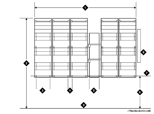
The 110A-type terminal blocks can be stacked in almost any arrangement at any height or location on the wall. One arrangement is shown in 110A-Type Terminal Blocks (300-Pair). The distance between the mounting screw holes on the terminal blocks is 10.8 in. (27.4 cm). If a vertical patch cord trough is used, the distance between the mounting screw holes is 5.31 in. (13.3 cm).
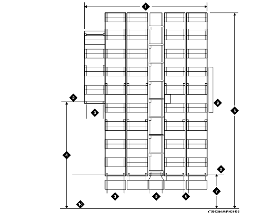
With 110P-type terminal blocks, the first block of the trunk/auxiliary field is aligned with the left side of the system cabinet. See 110P-Type Terminal Blocks (900-Pair). This arrangement allows for growth on the right side of the MDF.
- Route the cables from the rear of the cabinet stack to the MDF via the Cable Slack Manager. See Install Cable Slack Managers.
- If you are installing 300-pair terminal blocks, draw a level horizontal line on the wall 47.5 in. (1.2 m) above the floor. See 110A-Type Terminal Blocks (300-Pair).
If you are installing 900-pair terminal blocks, draw a level horizontal line on the wall 23 in. (58.4 cm) above the floor. See 110P-Type Terminal Blocks (900-Pair). - To mount the first trunk/auxiliary field terminal block, partially install 2 3/4-in. #12 wood screws, 7-11/16 in. (19.5 cm) apart on the left side of the horizontal line on the wall.
- Slide the bottom terminal block ft onto the mounting screws and mark the upper mounting screw locations.
- Remove the terminal block and partially install the upper mounting screws.
- Place the terminal block on the mounting screws and tighten the screws.
- If installing a vertical patch cord trough, partially install the first screw for the patch cord trough, on the line, 7/8-in. (2.2 cm) to the right of the previous screw. Partially install the second mounting screw 5.31 in. (13.5 cm) to the right of the screw just installed. Repeat Steps 4, 5, and 6.
- If another trunk/auxiliary field terminal block is to be installed, partially install the first screw for the terminal block, on the line, 7/8-in. (2.2 cm) to the right of the previous screw. Partially install the second mounting screw 7-11/16 in. (19.5 cm) to the right of the screw just installed. Repeat Steps 4, 5, and 6.
- If a horizontal patch cord trough is to be installed, install it, on the line, between the trunk/auxiliary field and the distribution field.
- To install the first distribution field terminal block, partially install 2 3/4-in., #12 wood screws, 7-11/16 in. (19.5 cm) apart on the line, to the right of the vertical patch cord trough. Repeat Steps 4, 5, and 6.
- If installing another distribution field terminal block, partially install the first screw for the terminal block, on the line, 7/8-in. (2.2 cm) to the right of the previous screw. Partially install the second mounting screw 7-11/16 in. (19.5 cm) to right of the screw just installed. Repeat Steps 4, 5, and 6.
- If installing a vertical patch cord trough in the distribution field, repeat Step 6.
- Repeat Steps 11 and 12 until all the terminal blocks and vertical patch cord troughs in the distribution field are installed.
110A-Type Terminal Blocks (300-Pair)
Figure Notes
110P-Type Terminal Blocks (900-Pair)
Figure Notes:
| Copyright� 2001 Avaya Inc. |
| Send comments to MadeEasy Development Team |
| Always check at the Made Easy Web site for the most current information. |

