DEFINITY Made Easy Tools
Issue 3, December 2001
Install and Connect Single-Carrier Cabinets
Installing on a wall with a plywood backing plate
- Hold the unit at the desired locaton and mark the four hole (slots and keyholes) centers with a pencil.
DEFINITY Made Easy Tools
Issue 3, December 2001
Install and Connect Single-Carrier Cabinets
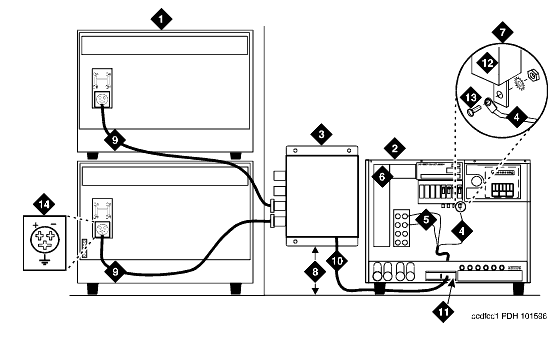
| Note: | The J58890CG DC Power Distribution Unit should be installed to the right of the SCC Cabinet Stack and mounted approximately 12 inches (30.5 cm) off the floor. |
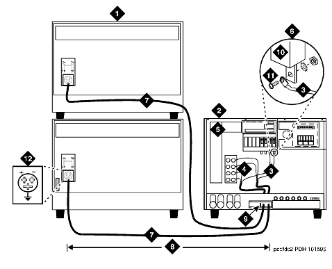
A 10 foot (3 meter) power cord is equipped with the appropriate connectors. In the configuration shown in Connections Using DC Power Distribution Unit, each cabinet stack has a DC Power Distribution Unit associated with it.
Up to three DC Power Cabinets can be stacked to supply power to Single-Carrier Cabinet stacks. See DC Power Cabinet Stack -- Rear.
Typical DC Power Connections
Connections Using DC Power Distribution Unit
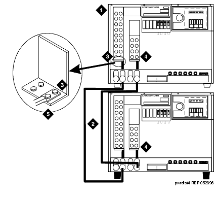
DC Power Cabinet Stack -- Rear
| Copyright� 2001 Avaya Inc. |
| Send comments to MadeEasy Development Team |
| Always check at the Made Easy Web site for the most current information. |