DEFINITY Made Easy Tools
Issue 3, December 2001
Install and Connect Single-Carrier Cabinets
Install Earthquake Protection for SCC
Earthquake protection installs only on Single-Carrier Cabinets.
- Position the Control Cabinet (J58890L) in the position it is to occupy when the installation is complete. Be sure the cabinet is level.
- Using a pencil or marker and using the Front Mounting Angle as a template, mark the locations of the two floor mounting holes.
- Move the cabinet out of the way and drill a hole 0.5-inch (1.3 cm) in diameter and 1.5 inches (3.8 cm) deep at the locations marked in Step 2.
- Insert a concrete floor anchor (STARR part number 3425) into each hole.
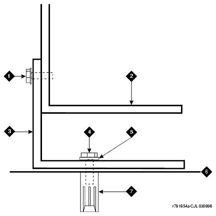
- Secure the Front Mounting Angle to the floor using the short hex head bolts provided.
- Move the cabinet back into place.
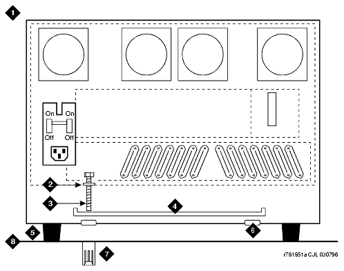
- At the rear of the cabinet, remove the two hole plugs from the bottom of the cabinet. See Cabinet Earthquake Mounting -- Rear View.
- Insert a pencil or marker through the holes in the bottom of the cabinet and mark the floor directly beneath each hole.
- Move the cabinet out of the way and drill a hole 0.5-inch (1.27 cm) in diameter and 1.5 inches (3.8 cm) deep at the locations marked in Step 8.
- Insert a concrete floor anchor (STARR part number 3425) into each hole.
- Move the cabinet back into place and align with the Front Mounting Angle.
- Attach the cabinet to the Front Mounting Angle using the four supplied #12-24 x 1/2-inch (1.27 cm) thread-forming screws. See Front Mounting Angle Location.
- Lay the supplied Stiffener on the bottom rear of the cabinet and align with the holes in the bottom of the cabinet. See Cabinet Earthquake Mounting -- Rear View.
- Slide a nylon washer onto each of the two supplied long hex head bolts.
- Insert the bolts through the Stiffener and thread into the concrete floor anchor. Tighten securely.

