DEFINITY Made Easy Tools
Issue 3, December 2001
Install Telecommunications Cabling
DEFINITY Made Easy Tools
Issue 3, December 2001
Install Telecommunications Cabling
| Note: | To route the cables from the rear of the SCC stack or MCC to the MDF, use the Install Cable Slack Managers procedure. Also see Cable Slack Manager. |
This section has information about
The purple port label shown in Equipment Room Cabling Labels is installed on both ends of the 25-pair cables connecting to the trunk/auxiliary field and/or distribution field.
The top blue/yellow building and floor labels are for cables connecting from the equipment room to a site/satellite location on another floor or in another building. The yellow label is for auxiliary circuits connecting to the trunk/auxiliary field. The bottom blue/yellow label is for 25-pair cables connecting to site/satellite closets.
Equipment Room Labels details the label name and range of each label.
Self-Stick Label on 25-Pair Cable Connector shows the proper way to install a label on a 25-pair cable connector. Install the label near the rear of the connector so it is not obscured by the cabinet connector retainers. It can also be installed on the skin of the cable near the connector.
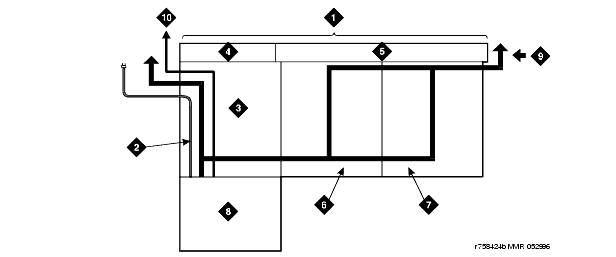
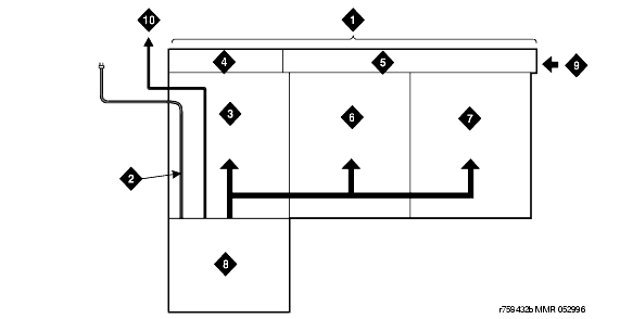
Cable Routing to Top Terminal Blocks and Cable Routing to Bottom Terminal Blocks show typical cable routing from the cabinet to the top and bottom of the MDF, respectively.
Use these guidelines when routing cables from the cabinet to the MDF. Following these guidelines will maximize use of the cable slack managers and make future cabling additions and changes easier.
| Note: | Retainers mounted on the columns keep the cable from protruding above the top of the base of the cable slack manager. |
A connector on the rear of the Control Carrier is labeled AUX. A 25-pair cable connects the AUX connector to a 110-type terminal block in the yellow field of the trunk/auxiliary field. The AUX connector outputs include the following:
The 1-pair of Central Office (CO) trunks are installed by the network provider in the green field. Up to 24 pairs may be terminated on each row of the 110-type terminal block. Tie trunks also appear in the green field with up to eight 3-pair trunks terminated on each row of the 110-type terminal block.
WP-90929, List 1 and 3 concentrator cables can be used to connect the cabinet to the 110-type terminal blocks in the purple field. The 1-pair patch cords/jumper wires are then run from the purple terminal block rows to the green terminal block rows in order to establish the correct 3-pair modularity.
Equipment Room Cabling Labels
Self-Stick Label on 25-Pair Cable Connector
Cable Routing to Top Terminal Blocks
Cable Routing to Bottom Terminal Blocks
| Copyright� 2001 Avaya Inc. |
| Send comments to MadeEasy Development Team |
| Always check at the Made Easy Web site for the most current information. |