You will be making fiber-optic connections between cabinets.
Select the procedure that best fits your location and reliability level from the table below:
Connecting standard or high reliability adjacent cabinets
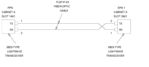
When a standard-reliability PPN and EPN are collocated, one fiber-optic cable (FL2P-P-XX) and two lightwave transceivers (9823-type) are required to connect the EPN.
- Behind control cabinet A of the single-carrier PPN (see Standard-Reliability Release 8si with Two Port Networks and Fiber-Optic Connections PPN to EPN (standard/high reliability adjacent cabinets)):
- Install a 9823-type lightwave transceiver on the connector at slot 1A01.
- Connect one end of the fiber-optic cable to the 9823-type lightwave transceiver at slot 1A01.
- Route the fiber-optic cable from the 9823-type lightwave transceiver to the cabinet's cable tray and downward out of the cabinet to the EPN stack.
- Behind control cabinet A of the single-carrier EPN:
- Install the same kind (either 9823-A or 9823-B) of lightwave transceiver on cable connector at slot 2A01.
- Connect the other end of the fiber-optic cable, coming from the PPN, to the 9823-type lightwave transceiver at slot 2A01.
- Carefully attach the fiber-optic cable (with cable ties) to the rear covers of the EPN stack.
- Coil up the surplus length of fiber-optic cable, and place the coil either in the cable manager or on the bottom shelf (holding the power supply) of the PPN cabinet.
Standard-Reliability Release 8si with Two Port Networks
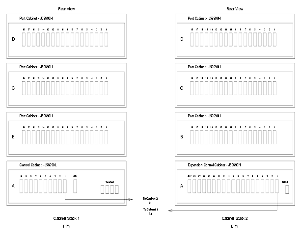
Fiber-Optic Connections PPN to EPN (standard/high reliability adjacent cabinets)
Return to Task List
Connecting standard or high reliability remote cabinets
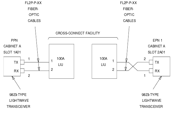
When a standard-reliability PPN and EPN are remotely separated with fiber, two fiber-optic cables (FL2P-P-XX), two lightwave transceivers (9823-type), and two lightwave-interface units (provided by the PSC) are required.
- Behind control cabinet A of the single-carrier PPN (Standard-Reliability Release 8si with Two Port Networks and Fiber-Optic Connections PPN to EPN (standard reliability remote cabinets)):
- Install a 9823-type lightwave transceiver on the connector at slot 1A01.
- Connect one end of the fiber-optic cable to the 9823-type lightwave transceiver at slot 1A01.
- Route the fiber-optic cable from the 9823-type lightwave transceiver to the cabinet cable tray and out of the cabinet through the cable manager to the PDS cross-connect facility.
- At the PDS cross-connect facility, connect the fiber-optic cable to the lightwave-interface unit provided.
- Delicately attach the fiber-optic cable (with cable ties) to the wall of the cable tray at the built-in cable-tie positions.
- Behind control cabinet A of the single-carrier EPN:
- Install the same kind (either 9823-A or 9823-B) of lightwave transceiver on cable connector at slot 2A01.
- Connect the fiber-optic cable to the 9823-type lightwave transceiver at slot 2A01.
- Route the fiber-optic cable from the 9823-type lightwave transceiver to the cabinet cable tray and out of the cabinet through the cable manager to the PDS cross-connect facility.
- At the PDS cross-connect facility, connect the fiber-optic cable to the lightwave-interface unit provided.
- Delicately attach the fiber-optic cable (with cable ties) to the rear covers of the EPN stack.
- Coil up the surplus length of fiber-optic cable, and place the coil in the cable manager.
Standard-Reliability Release 8si with Two Port Networks
Fiber-Optic Connections PPN to EPN (standard reliability remote cabinets)
Return to Task List
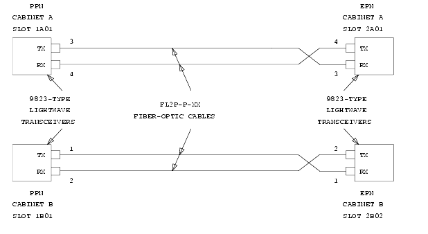
Connecting Critical Reliability adjacent cabinets
When a critical-reliability PPN and EPN are collocated, two fiber-optic cables (FL2P-P-XX) and four lightwave transceivers (9823-type) are required to connect the EPN.
- Behind control cabinet A of the single-carrier PPN (see Critical-Reliability Release 8si with Two Port Networks and Critical Reliability fiber optic connections (adjacent cabinets)):
- Install a 9823-type lightwave transceiver on the connector at slot 1A01.
- Connect one end of a fiber-optic cable to the 9823-type lightwave transceiver at slot 1A01.
- Route the fiber-optic cable from the 9823-type lightwave transceiver to the cabinet's cable tray and downward out of the cabinet to the EPN stack.
- Delicately attach the fiber-optic cable (with cable ties) to the wall of the cable tray at the built-in cable-tie positions.
- Behind control cabinet A of the single-carrier EPN:
- Install the same kind (either 9823-A or 9823-B) of lightwave transceiver on cable connector at slot 2A01.
- Connect the fiber-optic cable, coming from control cabinet A of the PPN, to the 9823-type lightwave transceiver at slot 2A01.
- Delicately attach the fiber-optic cable (with cable ties) to the rear covers of the EPN stack.
- Coil up the surplus length of fiber-optic cable, and place the coil either in the cable manager or on the bottom shelf (holding the power supply) of the PPN cabinet.
- Behind control cabinet B of the single-carrier PPN:
- Install a 9823-type lightwave transceiver on the connector at slot 1B01.
- Connect one end of a fiber-optic cable to the 9823-type lightwave transceiver at slot 1B01.
- Route the fiber-optic cable from the 9823-type lightwave transceiver to the cabinet's cable tray and downward out of the cabinet to the EPN stack.
- Delicately attach the fiber-optic cable (with cable ties) to the wall of the cable tray at the built-in cable-tie positions.
- Behind port cabinet B of the single-carrier EPN:
- Install the same kind (either 9823-A or 9823-B) of lightwave transceiver on cable connector at slot 2B02.
- Connect the fiber-optic cable, coming from control cabinet B of the PPN, to the 9823-type lightwave transceiver at slot 2B02.
- Delicately attach the fiber-optic cable (with cable ties) to the rear covers of the EPN stack.
- Coil up the surplus length of fiber-optic cable, and place the coil either in the cable manager or on the bottom shelf (holding the power supply) of the PPN cabinet.
Critical-Reliability Release 8si with Two Port Networks
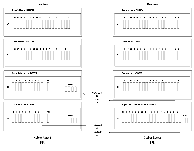
Critical Reliability fiber optic connections (adjacent cabinets)
Return to Task List
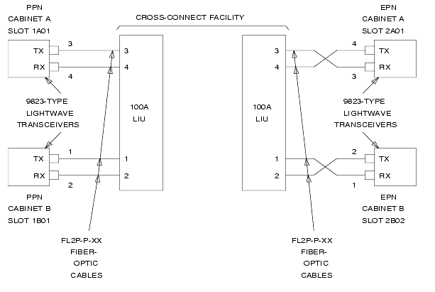
Connecting critical reliability remote cabinets
When a critical-reliability PPN and EPN are remotely separated with fiber, four fiber-optic cables (FL2P-P-XX), four lightwave transceivers (9823-type), and four lightwave-interface units (provided by the PSC) are required.
- Behind control cabinet A of the single-carrier PPN (see Critical-Reliability Release 8si with Two Port Networks and Critical Reliability fiber-optic connections (remote)):
- Install a 9823-type lightwave transceiver on the connector at slot 1A01.
- Connect one end of a fiber-optic cable to the 9823-type lightwave transceiver at slot 1A01.
- Route the fiber-optic cable from the 9823-type lightwave transceiver to the cabinet cable tray and out of the cabinet through the cable manager to the PDS cross-connect facility.
- At the PDS cross-connect facility, connect the fiber-optic cable to the lightwave-interface unit provided.
- Delicately attach the fiber-optic cable (with cable ties) to the wall of the cable tray at the built-in cable-tie positions.
- Behind control cabinet A of the single-carrier EPN:
- Install the same kind (either 9823-A or 9823-B) of lightwave transceiver on cable connector at slot 2A01.
- Connect the fiber-optic cable, coming from control cabinet A of the PPN, to the 9823-type lightwave transceiver at slot 2A01.
- Route the fiber-optic cable from the 9823-type lightwave transceiver to the cabinet cable tray and out of the cabinet through the cable manager to the PDS cross-connect facility.
- At the PDS cross-connect facility, connect the fiber-optic cable to the lightwave-interface unit provided.
- Delicately attach the fiber-optic cable (with cable ties) to the rear covers of the EPN stack.
- Coil up the surplus length of fiber-optic cable, and place the coil in the cable manager.
- Behind control cabinet B of the single-carrier PPN:
- Install a 9823-type lightwave transceiver on the connector at slot 1B01.
- Connect one end of a fiber-optic cable to the 9823-type lightwave transceiver at slot 1B01.
- Route the fiber-optic cable from the 9823-type lightwave transceiver to the cabinet cable tray and out of the cabinet through the cable manager to the PDS cross-connect facility.
- At the PDS cross-connect facility, connect the fiber-optic cable to the lightwave-interface unit provided.
- Delicately attach the fiber-optic cable (with cable ties) to the wall of the cable tray at the built-in cable-tie positions.
- Behind port cabinet B of the single-carrier EPN:
- Install the same kind (either 9823-A or 9823-B) of lightwave transceiver on cable connector at slot 2B02.
- Connect the fiber-optic cable, coming from control cabinet B of the PPN, to the 9823-type lightwave transceiver at slot 2B02.
- Route the fiber-optic cable from the 9823-type lightwave transceiver to the cabinet cable tray and out of the cabinet through the cable manager to the PDS cross-connect facility.
- At the PDS cross-connect facility, connect the fiber-optic cable to the lightwave-interface unit provided.
- Delicately attach the fiber-optic cable (with cable ties) to the wall of the cable tray at the built-in cable-tie positions.
- Coil up the surplus length of fiber-optic cable, and place the coil in the cable manager.
Critical-Reliability Release 8si with Two Port Networks
Critical Reliability fiber-optic connections (remote)
Return to Task List