- Connect the fiber optic cable.
The Customer Service Document (CSD) provides an "Inter-Cabinet Cable Running List." Each row on the list represents a cable connection. Use the running list to determine where to connect each fiber optic cable.
For standard reliability fiber connections: see Connections to Standard Reliability Systems for a sample cable routing.
For high reliability fiber connections: see Connections to High Reliability Systems for a sample cable routing.
For Critical Reliability Fiber Connections: see Connections to Critical Reliability Systems for a sample cable routing.
- Route the fiber optic cable up toward the top of the cabinet. The excess cable should be looped and draped from the B25A cable clamp on the top ground plate in the stack. See Single-Carrier Cabinet Fiber Routing.
- Dress the cable by tie wrapping it to the outside of the B25A cable clamp.
Connections for High or Critical Reliability Systems
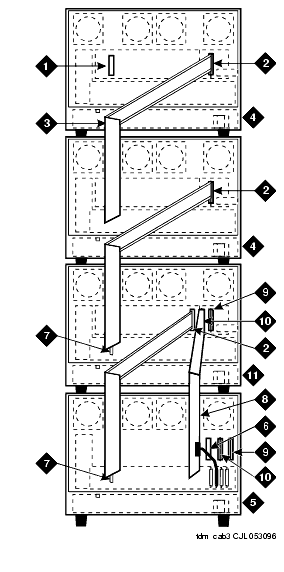
Figure Notes:
- AHF110 TDM Bus Terminator (Slot 17)
- TDM/Local Area Network (TDM/LAN) Pinfield (Slot 00)
- TDM bus Cable (WP-91716 L3)
- Port Cabinet
- Control Cabinet A Position
- AHF110 TDM Bus Terminator (Slot 01)
- Slot 18
- Inter-Cabinet Cables (ICC) A, B and C (H600-248-G1)
- Inter-Cabinet Cable (ICC) A
- Inter-Cabinet Cable (ICC) B
- Duplicated Control Cabinet B Position
.
Single-Carrier Cabinet Fiber Routing
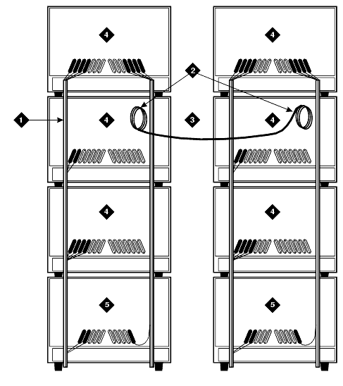
Figure Notes:
- Supplied B25A Cables
- Loop and Drape Excess Fiber Optic Cable
- Fiber Optic Cable Sheath
- Port Cabinet
- Control Cabinet
Connections to Standard Reliability Systems
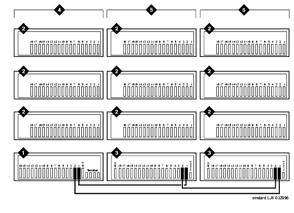
Figure Notes:
- Control Cabinet
- Port Cabinet
- Expansion Control Cabinet
- Cabinet Stack 1
- Cabinet Stack 2
- Cabinet Stack 3
Connections to High Reliability Systems
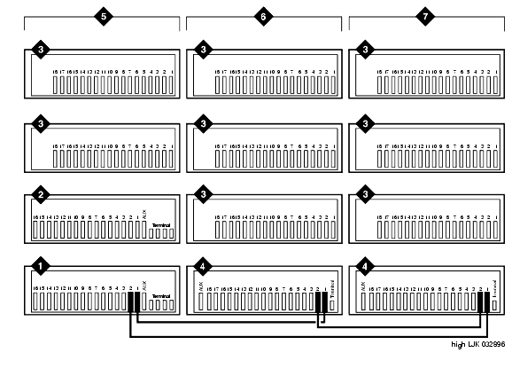
Figure Notes:
- Control Cabinet
- Duplicate Control Cabinet
- Port Cabinet
- Expansion Control Cabinet
- Cabinet Stack 1
- Cabinet Stack 2
- Cabinet Stack 3
Connections to Critical Reliability Systems
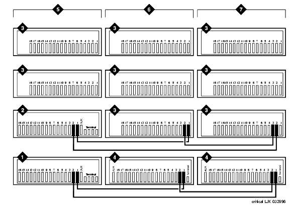
Figure Notes:
- Control Cabinet
- Duplicate Control Cabinet
- Port Cabinet
- Expansion Control Cabinet
- Cabinet Stack 1
- Cabinet Stack 2
- Cabinet Stack 3
Return to Task List


