Make the Remaining Connections
Return to Task List
For a fiber-remoted SCC EPN, see UPS for Fiber-Remoted SCC EPN. For a DS1-remoted SCC EPN and associated CSUs, see UPS for DS1 Remoted SCC EPN.
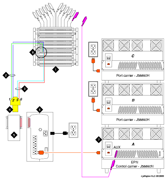
- Plug the 700A8 plug into the Z3A2 UPS alarm adapter.
- Connect the alarm adapter to the UPS DB25 RS-232 serial port connector.
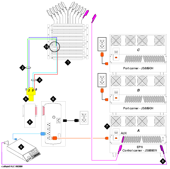
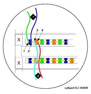
- Connect the wires from the plug to the 110 cross-connect field for the AUX connector (see Wire Connections and Enlarged View of the 110 Cross-Connect Field for the AUX Connector).
If connecting a UPS for a DS1-remoted SCC EPN:
- Plug the CSU(s) used in the A-level DS1 converter into the UPS.
UPS for Fiber-Remoted SCC EPN

Figure Notes:
- 110 cross-connect field
- Utility fail wire pair
- UPS fail wire pair
- 700A8 (RJ45) modular plug (see Wire the 700A8 Plug for wiring detail)
- Z3A2 UPS alarm adapter plugs into DB25 connector
- UPS 800/1000VA
- EPN control carrier
- See Enlarged View of the 110 Cross-Connect Field for the AUX Connector for wiring detail
UPS for DS1 Remoted SCC EPN

Figure Notes:
- 110 cross-connect field
- Utility fail wire pair
- UPS fail wire pair
- 700A8 (RJ45) modular plug (see Wiring the 700A8 Plug for wiring detail)
- Z3A2 UPS alarm adapter plugs into DB25 connector
- UPS 800/1000VA
- EPN control carrier
- H600-348 DS1 converter cable
- Channel service unit
- See Enlarged View of the 110 Cross-Connect Field for the AUX Connector for wiring detail
Enlarged View of the 110 Cross-Connect Field for the AUX Connector

Figure Notes:
- Utility fail wire pair:
- 1M (major alarm)
- return GRD
- UPS fail wire pair:
- 1m (minor alarm)
- return GRD
Return to Task List


